HSRP Configuration IPv4 and IPv6 - Router Redundancy Guide
- What is HSRP? ‹
- HSRP configuration on physical interface ‹
- HSRP configuration on SVI (virtual interface) ‹
- HSRP configuration on VRF subinterface ‹
- HSRP configuration over IPv6 ‹
- Object tracking and return traffic ‹
- Download section ‹
What is HSRP?
HSRP (Hot Standby Router Protocol) enables a redundant pair of gateway routers to act as a single virtual device towards hosts in a LAN. Hosts can point a default route to the virtual IP address created with HSRP. In the event of an HSRP primary router failure, the virtual IP address remains unchanged. Failover to the HSRP backup router is transparent to the hosts which keep using the virtual IP address.
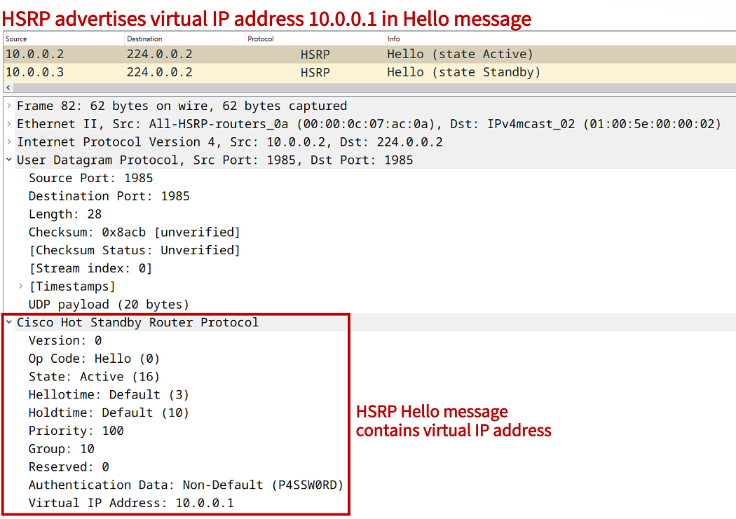
The above packet capture reveals that HSRP messages are sent to the multicast address 224.0.0.2. The roles of Active or Standby are assigned by HSRP to participating routers. The default timers used by HSRP are also visible. A Hello message is sent every 3 seconds by default, and an Active/Standby state change is initiated if an HSRP peer does not send a Hello within 10 seconds (Holdtime).
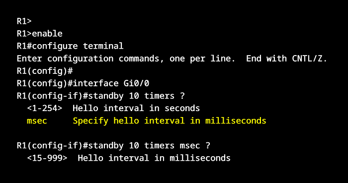
However, HSRP is capable of sub-second failure detection and failover, this is one of its main advantages. HSRP authentication is also visible in both packet captures (above and below), but it is turned off by default. Notice that HSRP messages are encapsulated with a UDP header, which uses the port 1985.

Another important aspect of HSRP is the virtual MAC address. This is the source MAC address in HSRP Hello messages sent from the Active device, and it is 0000:0C07:AC##. The last two hexadecimal characters define the HSRP Group number being used. For example, HSRP Group 10 receives the virtual MAC address 0000:0C07:AC0A. This address is learned on a connected Layer-2 device (such as a switch).
Switch#show mac address-table
          Mac Address Table
-------------------------------------------

Vlan    Mac Address       Type        Ports
----    -----------       --------    -----
   1    0000.0c07.ac0a    DYNAMIC     Gi0/1                 « HSRP version 1 virtual MAC address
   1    5254.0000.f828    DYNAMIC     Gi0/0
   1    5254.000c.acd0    DYNAMIC     Gi0/2
   1    5254.000e.bae6    DYNAMIC     Gi0/1
Total Mac Addresses for this criterion: 4


Switch#show mac address-table
          Mac Address Table
-------------------------------------------

Vlan    Mac Address       Type        Ports
----    -----------       --------    -----
   1    0000.0c9f.f00a    DYNAMIC     Gi0/1                 « HSRP version 2 virtual MAC address
   1    5254.0000.f828    DYNAMIC     Gi0/0
   1    5254.000c.acd0    DYNAMIC     Gi0/2
   1    5254.000e.bae6    DYNAMIC     Gi0/1
Total Mac Addresses for this criterion: 4
This blog post focuses on HSRP version 1 which is the default when configured. There is however also HSRP version 2 which uses a different multicast IP and MAC address, and has a different packet structure. HSRP version 2 has several benefits over version 1, and in order to configure HSRP over IPv6 it is necessary to use HSRPv2.
HSRP configuration on physical interface
In the following example scenario, HSRP Group 10 is configured between redundant gateway routers R1 and R2. The configuration is applied under the physical interface Gi0/0 on both routers. The HSRP virtual IP address 10.0.0.1 is advertised within Site 1. The Host points a default route towards the vIP. If the HSRP priority is not configured, it defaults to 100. This is how R1 becomes the Active (primary) device.

Configuration:
R1
R1#show run int Gi0/0 | sec int
interface GigabitEthernet0/0
 description ** to Site 1 **
 ip address 10.0.0.2 255.255.255.0
 standby 10 ip 10.0.0.1
 standby 10 preempt
 standby 10 authentication P4SSW0RD
 duplex auto
 speed auto
 media-type rj45

R1#show run int Gi0/1 | sec int
interface GigabitEthernet0/1
 description ** to internet **
 ip address 172.16.1.1 255.255.255.252
 duplex auto
 speed auto
 media-type rj45

R1#show run | sec ^ip route
ip route 0.0.0.0 0.0.0.0 GigabitEthernet0/1 172.16.1.2
R2
R2#show run int Gi0/0 | sec int
interface GigabitEthernet0/0
 description ** to Site 1 **
 ip address 10.0.0.3 255.255.255.0
 standby 10 ip 10.0.0.1
 standby 10 priority 90
 standby 10 preempt
 standby 10 authentication P4SSW0RD
 duplex auto
 speed auto
 media-type rj45

R2#show run int Gi0/1 | sec int
interface GigabitEthernet0/1
 description ** to internet **
 ip address 172.16.2.1 255.255.255.252
 duplex auto
 speed auto
 media-type rj45

R2#show run | sec ^ip route
ip route 0.0.0.0 0.0.0.0 GigabitEthernet0/1 172.16.2.2
Host
Host#show run int Gi0/0 | sec int
interface GigabitEthernet0/0
 description ** to R2 and R3 **
 ip address 10.0.0.4 255.255.255.0
 duplex auto
 speed auto
 media-type rj45

Host#show run | sec ^ip route
ip route 0.0.0.0 0.0.0.0 GigabitEthernet0/0 10.0.0.1
R1#show standby all
GigabitEthernet0/0 - Group 10
  State is Active
    2 state changes, last state change 00:05:05
  Virtual IP address is 10.0.0.1
  Active virtual MAC address is 0000.0c07.ac0a
    Local virtual MAC address is 0000.0c07.ac0a (v1 default)
  Hello time 3 sec, hold time 10 sec
    Next hello sent in 1.120 secs
  Authentication text, string "P4SSW0RD"
  Preemption enabled
  Active router is local
  Standby router is 10.0.0.3, priority 90 (expires in 10.496 sec)
  Priority 100 (default 100)                 « HSRP default priority is 100
  Group name is "hsrp-Gi0/0-10" (default)


R1#show standby brief
                     P indicates configured to preempt.
                     |
Interface   Grp  Pri P State   Active          Standby         Virtual IP
Gi0/0       10   100 P Active  local           10.0.0.3        10.0.0.1     « R2 is the Standby (backup) router


Host#trace 172.16.0.1 probe 1
Type escape sequence to abort.
Tracing the route to 172.16.0.1
VRF info: (vrf in name/id, vrf out name/id)
  1 10.0.0.2 3 msec               « Before failure default is R1 Active router
  2 172.16.1.2 3 msec
  3 172.16.0.1 3 msec


R2#show log | beg Log Buffer
Log Buffer (8192 bytes):

%HSRP-5-STATECHANGE: GigabitEthernet0/0 Grp 10 state Standby -> Active      « State change during R1 failure


Host#trace 172.16.0.1 probe 1
Type escape sequence to abort.
Tracing the route to 172.16.0.1
VRF info: (vrf in name/id, vrf out name/id)
  1 10.0.0.3 2 msec               « New route through backup router which is now HSRP Active
  2 172.16.2.2 2 msec
  3 172.16.0.1 4 msec
In the above outputs it is visible how failure of the HSRP Active router R1 causes automatic switchover to the backup path through R2. By configuring the HSRP debug standby events command, further details about the switchover are displayed in the router logs. For example, creation of a Gratuitous ARP (GARP) packet is visible on R2.
R2#show log | beg Log Buffer
Log Buffer (8192 bytes):

HSRP: Gi0/0 Grp 10 Standby: i/Resign rcvd (100/10.0.0.2)
HSRP: Gi0/0 Grp 10 Active router is local, was 10.0.0.2
HSRP: Gi0/0 Nbr 10.0.0.2 no longer active for group 10 (Standby)
HSRP: Gi0/0 Nbr 10.0.0.2 Was active or standby - start passive holddown
HSRP: Gi0/0 Grp 10 Standby router is unknown, was local
HSRP: Gi0/0 Grp 10 Standby -> Active
%HSRP-5-STATECHANGE: GigabitEthernet0/0 Grp 10 state Standby -> Active
HSRP: Gi0/0 Grp 10 Redundancy "hsrp-Gi0/0-10" state Standby -> Active
HSRP: Gi0/0 Grp 10 Added 10.0.0.1 to ARP (0000.0c07.ac0a)
HSRP: Gi0/0 Grp 10 Activating MAC 0000.0c07.ac0a
HSRP: Gi0/0 Grp 10 Adding 0000.0c07.ac0a to MAC address filter
HSRP: Gi0/0 IP Redundancy "hsrp-Gi0/0-10" standby, local -> unknown
HSRP: Gi0/0 IP Redundancy "hsrp-Gi0/0-10" update, Standby -> Active
HSRP: Gi0/0 IP Redundancy "hsrp-Gi0/0-10" update, Active -> Active
R2#
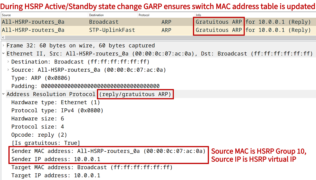
The GARP packet is sent by the new HSRP Active router. When a connected switch receives the GARP packet, it can update its MAC address table to reflect the HSRP state change. The following outputs from the connected switch show the HSRP Active router is reachable through a different switchport (due to HSRP traffic failover).
SW#show mac address-table
          Mac Address Table
-------------------------------------------

Vlan    Mac Address       Type        Ports
----    -----------       --------    -----
   1    0000.0c07.ac0a    DYNAMIC     Gi0/1
   1    5254.0000.f828    DYNAMIC     Gi0/0
   1    5254.000c.acd0    DYNAMIC     Gi0/2
   1    5254.000e.bae6    DYNAMIC     Gi0/1
Total Mac Addresses for this criterion: 4


SW#show mac address-table
          Mac Address Table
-------------------------------------------

Vlan    Mac Address       Type        Ports
----    -----------       --------    -----
   1    0000.0c07.ac0a    DYNAMIC     Gi0/2
   1    5254.0000.f828    DYNAMIC     Gi0/0
   1    5254.000c.acd0    DYNAMIC     Gi0/2
   1    5254.000e.bae6    DYNAMIC     Gi0/1
Total Mac Addresses for this criterion: 4
HSRP configuration on SVI (virtual interface)
In the following example scenario, HSRP is configured on the Switch Virtual Interface (SVI) of SW1 and SW2. Both devices are Layer-3 switches, which means they are able route IP packets in addition to the traditional Layer-2 functions. VLAN 10 is configured throughout this example network, and the trunk ports on each switch restrict traffic to VLAN 10 only.

Configuration:
SW1
SW1#show run int vlan 10 | sec int
interface Vlan10
 description ** SVI for VLAN 10 **
 ip address 10.0.0.2 255.255.255.0
 standby 10 ip 10.0.0.1
 standby 10 preempt
 standby 10 authentication P4SSW0RD

SW1#show run int Gi0/0 | sec int
interface GigabitEthernet0/0
 description ** trunk to Site 1 **
 switchport trunk allowed vlan 10
 switchport trunk encapsulation dot1q
 switchport mode trunk
 negotiation auto

SW1#show run int Gi0/1 | sec int
interface GigabitEthernet0/1
 description ** to internet **
 no switchport
 ip address 172.16.1.1 255.255.255.252
 negotiation auto

SW1#show run | sec ^ip route
ip route 0.0.0.0 0.0.0.0 GigabitEthernet0/1 172.16.1.2
SW2
SW2#show run int vlan 10 | sec int
interface Vlan10
 description ** SVI for VLAN 10 **
 ip address 10.0.0.3 255.255.255.0
 standby 10 ip 10.0.0.1
 standby 10 priority 90
 standby 10 preempt
 standby 10 authentication P4SSW0RD

SW2#show run int Gi0/0 | sec int
interface GigabitEthernet0/0
 description ** trunk to Site 1 **
 switchport trunk allowed vlan 10
 switchport trunk encapsulation dot1q
 switchport mode trunk
 negotiation auto

SW2#show run int Gi0/1 | sec int
interface GigabitEthernet0/1
 description ** to internet **
 no switchport
 ip address 172.16.2.1 255.255.255.252
 negotiation auto

SW2#show run | sec ^ip route
ip route 0.0.0.0 0.0.0.0 GigabitEthernet0/1 172.16.2.2
SW3
SW3#show run int Gi0/0 | sec int
interface GigabitEthernet0/0
 switchport access vlan 10
 switchport mode access
 negotiation auto

SW3#show run int Gi0/1 | sec int
interface GigabitEthernet0/1
 description ** to SW1 **
 switchport trunk allowed vlan 10
 switchport trunk encapsulation dot1q
 switchport mode trunk
 negotiation auto

SW3#show run int Gi0/2 | sec int
interface GigabitEthernet0/2
 description ** to SW2 **
 switchport trunk allowed vlan 10
 switchport trunk encapsulation dot1q
 switchport mode trunk
 negotiation auto
SW1#show standby brief
                     P indicates configured to preempt.
                     |
Interface   Grp  Pri P State   Active          Standby         Virtual IP
Vl10        10   100 P Active  local           10.0.0.3        10.0.0.1


SW1#show standby all
Vlan10 - Group 10
  State is Active
    4 state changes, last state change 00:15:46
  Virtual IP address is 10.0.0.1
  Active virtual MAC address is 0000.0c07.ac0a (MAC In Use)
    Local virtual MAC address is 0000.0c07.ac0a (v1 default)
  Hello time 3 sec, hold time 10 sec
    Next hello sent in 1.328 secs
  Authentication text, string "P4SSW0RD"
  Preemption enabled
  Active router is local
  Standby router is 10.0.0.3, priority 90 (expires in 9.952 sec)
  Priority 100 (default 100)
  Group name is "hsrp-Vl10-10" (default)


SW1#show arp
Protocol  Address          Age (min)  Hardware Addr   Type   Interface
Internet  10.0.0.1                -   0000.0c07.ac0a  ARPA   Vlan10              « HSRP vIP and MAC address associated with SVI
Internet  10.0.0.2                -   5254.0001.800a  ARPA   Vlan10
Internet  10.0.0.4                0   5254.0000.f828  ARPA   Vlan10
Internet  172.16.1.1              -   5254.0019.2dad  ARPA   GigabitEthernet0/1
Internet  172.16.1.2             16   5254.001e.1bc3  ARPA   GigabitEthernet0/1
HSRP configuration on VRF subinterface
In the following example scenario a VRF subinterface is configured on R1 and on R2 using VRF Gold together with VLAN 10. HSRP is configured on the VRF subinterface. This design is very common in dual-CE MPLS Layer-3 VPN deployments.

Configuration:
R1
R1#show run int Gi0/0.10 | sec int
interface GigabitEthernet0/0.10
 description ** VRF subinterface - VLAN 10 **
 encapsulation dot1Q 10
 vrf forwarding Gold
 ip address 10.0.0.2 255.255.255.0
 standby 10 ip 10.0.0.1
 standby 10 preempt
 standby 10 authentication P4SSW0RD

R1#show run int Gi0/0 | sec int
interface GigabitEthernet0/0
 description ** physical interface to Site 1 **
 no ip address
 duplex auto
 speed auto

R1#show run | sec ^vrf
vrf definition Gold
 rd 1:1
 !
 address-family ipv4
 exit-address-family
R2
R2#show run int Gi0/0.10 | sec int
interface GigabitEthernet0/0.10
 description ** VRF subinterface - VLAN 10 **
 encapsulation dot1Q 10
 vrf forwarding Gold
 ip address 10.0.0.3 255.255.255.0
 standby 10 ip 10.0.0.1
 standby 10 priority 90
 standby 10 preempt
 standby 10 authentication P4SSW0RD

R2#show run int Gi0/0 | sec int
interface GigabitEthernet0/0
 description ** physical interface to Site 1 **
 no ip address
 duplex auto
 speed auto

R2#show run | sec ^vrf
vrf definition Gold
 rd 1:1
 !
 address-family ipv4
 exit-address-family
SW
SW#show run int Gi0/0 | sec int
interface GigabitEthernet0/0
 switchport access vlan 10
 switchport mode access
 negotiation auto

SW#show run int Gi0/1 | sec int
interface GigabitEthernet0/1
 description ** to SW1 **
 switchport trunk allowed vlan 10
 switchport trunk encapsulation dot1q
 switchport mode trunk
 negotiation auto

SW#show run int Gi0/2 | sec int
interface GigabitEthernet0/2
 description ** to SW2 **
 switchport trunk allowed vlan 10
 switchport trunk encapsulation dot1q
 switchport mode trunk
 negotiation auto
R1#show standby brief
                     P indicates configured to preempt.
                     |
Interface   Grp  Pri P State   Active          Standby         Virtual IP
Gi0/0.10    10   100 P Active  local           10.0.0.3        10.0.0.1


R1#show standby
GigabitEthernet0/0.10 - Group 10
  State is Active
    1 state change, last state change 00:16:50
  Virtual IP address is 10.0.0.1
  Active virtual MAC address is 0000.0c07.ac0a
    Local virtual MAC address is 0000.0c07.ac0a (v1 default)
  Hello time 3 sec, hold time 10 sec
    Next hello sent in 1.728 secs
  Authentication text, string "P4SSW0RD"
  Preemption enabled
  Active router is local
  Standby router is 10.0.0.3, priority 90 (expires in 9.984 sec)
  Priority 100 (default 100)
  Group name is "hsrp-Gi0/0.10-10" (default)


Host#ping 10.0.0.1
Type escape sequence to abort.
Sending 5, 100-byte ICMP Echos to 10.0.0.1, timeout is 2 seconds:
!!!!!
Success rate is 100 percent (5/5), round-trip min/avg/max = 2/2/3 ms
HSRP configuration over IPv6
In the following example scenario HSRP is configured over IPv6, which requires the use of HSRPv2. A virtual IPv6 address is autoconfigured instead of manually assigned. The address is created with the EUI-64 method based on the HSRP IPv6 virtual MAC address 0005.73A0.0XXX. It allows for 4096 unique HSRP Groups. Since HSRP Group 10 is configured in this example, the virtual MAC address is 0005.73A0.000A.
The Host uses SLAAC to receive IPv6 prefix information. It autoconfigures the HSRP link-local (virtual) IPv6 address which is included in ICMPv6 Router Advertisement (RA) messages sent by R1 and R2. Furthermore, in the event of an HSRP state change, Neighbor Advertisement (NA) messages are advertised to update the MAC address table on the connected switch. There is no ARP in IPv6.

Configuration:
R1
R1#show run | sec ^ipv6 uni
ipv6 unicast-routing

R1#show run int Gi0/0 | sec int
interface GigabitEthernet0/0
 description ** to Site 1 **
 no ip address
 standby version 2
 standby 10 ipv6 autoconfig
 standby 10 preempt
 standby 10 authentication P4SSW0RD
 duplex auto
 speed auto
 ipv6 address FE80::2 link-local
 ipv6 address 2001:DB8::2/64

R1#show run int Gi0/1 | sec int
interface GigabitEthernet0/1
 description ** to internet **
 no ip address
 duplex auto
 speed auto
 media-type rj45
 ipv6 address 2001:DB8:1::1/64

R1#show run | sec ^ipv6 route
ipv6 route ::/0 GigabitEthernet0/1 2001:DB8:1::2
R2
R2#show run | sec ^ipv6 uni
ipv6 unicast-routing

R2#show run int Gi0/0 | sec int
interface GigabitEthernet0/0
 description ** to Site 1 **
 no ip address
 standby version 2
 standby 10 ipv6 autoconfig
 standby 10 priority 90
 standby 10 preempt
 standby 10 authentication P4SSW0RD
 duplex auto
 speed auto
 ipv6 address FE80::3 link-local
 ipv6 address 2001:DB8::3/64

R2#show run int Gi0/1 | sec int
interface GigabitEthernet0/1
 description ** to internet **
 no ip address
 duplex auto
 speed auto
 media-type rj45
 ipv6 address 2001:DB8:2::1/64

R2#show run | sec ^ipv6 route
ipv6 route ::/0 GigabitEthernet0/1 2001:DB8:2::2
Host
Host#show run int Gi0/0 | sec int
interface GigabitEthernet0/0
 no ip address
 duplex auto
 speed auto
 ipv6 address autoconfig default
 ipv6 enable
R1#show standby brief
                     P indicates configured to preempt.
                     |
Interface   Grp  Pri P State   Active          Standby         Virtual IP
Gi0/0       10   100 P Active  local           FE80::3         FE80::5:73FF:FEA0:A    « HSRP IPv6 vIP


R1#show standby
GigabitEthernet0/0 - Group 10 (version 2)
  State is Active
    4 state changes, last state change 01:22:48
  Link-Local Virtual IPv6 address is FE80::5:73FF:FEA0:A (conf auto EUI64)            « Virtual IP is created with EUI-64 method
  Active virtual MAC address is 0005.73a0.000a
    Local virtual MAC address is 0005.73a0.000a (v2 IPv6 default)
  Hello time 3 sec, hold time 10 sec
    Next hello sent in 0.144 secs
  Authentication text, string "P4SSW0RD"
  Preemption enabled
  Active router is local
  Standby router is FE80::3, priority 90 (expires in 10.784 sec)
  Priority 100 (default 100)
  Group name is "hsrp-Gi0/0-10" (default)


Host#trace 2001:DB8:A::1
Type escape sequence to abort.
Tracing the route to 2001:DB8:A::1

  1 2001:DB8::2 8 msec 2 msec 3 msec                 « Before failover R1 is the HSRP Active router
  2 2001:DB8:1::2 4 msec 3 msec 4 msec
  3 2001:DB8:A::1 4 msec 4 msec 4 msec


R2#show log | beg Log Buffer
Log Buffer (8192 bytes):

HSRP: Gi0/0 Grp 10 Standby: i/Resign rcvd (100/FE80::2)
HSRP: Gi0/0 Grp 10 Active router is local, was FE80::2
HSRP: Gi0/0 Nbr FE80::2 no longer active for group 10 (Standby)
HSRP: Gi0/0 Nbr FE80::2 Was active or standby - start passive holddown
HSRP: Gi0/0 Grp 10 Standby router is unknown, was local
HSRP: Gi0/0 Grp 10 Standby -> Active
%HSRP-5-STATECHANGE: GigabitEthernet0/0 Grp 10 state Standby -> Active          « Failover happens, R2 becomes new HSRP Active router
HSRP: Gi0/0 Grp 10 Activating MAC 0005.73a0.000a                                « R2 sends NDP Neighbor Advertisement with HSRP virtual MAC
HSRP: Gi0/0 Grp 10 Adding 0005.73a0.000a to MAC address filter


Host#trace 2001:DB8:A::1
Type escape sequence to abort.
Tracing the route to 2001:DB8:A::1

  1 2001:DB8::3 3 msec 3 msec 2 msec                 « After failover the traffic is routed through R2
  2 2001:DB8:2::2 3 msec 3 msec 3 msec
  3 2001:DB8:A::1 5 msec 4 msec 3 msec


Host#show ipv6 route
IPv6 Routing Table - default - 4 entries
Codes: C - Connected, L - Local, S - Static, U - Per-user Static route
       B - BGP, HA - Home Agent, MR - Mobile Router, R - RIP
       H - NHRP, I1 - ISIS L1, I2 - ISIS L2, IA - ISIS interarea
       IS - ISIS summary, D - EIGRP, EX - EIGRP external, NM - NEMO
       ND - ND Default, NDp - ND Prefix, DCE - Destination, NDr - Redirect
       RL - RPL, O - OSPF Intra, OI - OSPF Inter, OE1 - OSPF ext 1
       OE2 - OSPF ext 2, ON1 - OSPF NSSA ext 1, ON2 - OSPF NSSA ext 2
       la - LISP alt, lr - LISP site-registrations, ld - LISP dyn-eid
       lA - LISP away, a - Application
ND  ::/0 [2/0]
     via FE80::5:73FF:FEA0:A, GigabitEthernet0/0     « Default route to HSRP virtual IP address received through Neighbor Discovery (ND)
NDp 2001:DB8::/64 [2/0]
     via GigabitEthernet0/0, directly connected
L   2001:DB8::5054:FF:FE00:F828/128 [0/0]
     via GigabitEthernet0/0, receive
L   FF00::/8 [0/0]
     via Null0, receive


Host#show ipv6 route ::/0
Routing entry for ::/0
  Known via "ND", distance 2, metric 0
  Route count is 1/1, share count 0
  Routing paths:
    FE80::5:73FF:FEA0:A, GigabitEthernet0/0
      From FE80::5:73FF:FEA0:A
      Last updated 01:41:17 ago
Object tracking and return traffic
There are numerous features and benefits that can be unlocked by combining HSRP with object tracking and IP SLA. One such feature is triggering an HSRP traffic switchover if a connected internet link is down. In this case, traffic can be sent out on an available backup path.
It is important to note, even if traffic is sent out on a backup link after an HSRP switchover, it needs to be ensured that the return path of traffic will also be through the same backup link. With HSRP it is important to verify the different failure scenarios and how they influence bidirectional traffic flows. This is espacially true if there is also a crosslink which directly connects two HSRP routers, and if a routing protocol is configured on the crosslink.