Q-in-Q Introduction, Configuration, Packet Analysis
Table of Contents
Jump to section:
- • What is Q-in-Q?
- • What is the difference between 802.1Q and QinQ?
- • Q-in-Q configuration with CVLAN and SVLAN
- • Layer-2 Protocol Tunneling configuration
- • Native VLAN tagging
- • Configuring L2PT and EtherChannel with Q-in-Q
- • Provider switches learn duplicate MAC addresses with Independent VLAN Learning (IVL)
- • Download section
- What is Q-in-Q? ‹
- What is the difference between 802.1Q and Q-in-Q? ‹
- Q-in-Q configuration with CVLAN and SVLAN ‹
- Layer-2 Protocol Tunneling configuration ‹
- Native VLAN tagging ‹
- Configuring L2PT and EtherChannel with Q-in-Q ‹
- Provider switches learn duplicate MAC addresses with Independent VLAN Learning (IVL) ‹
- Download section ‹
What is Q-in-Q?
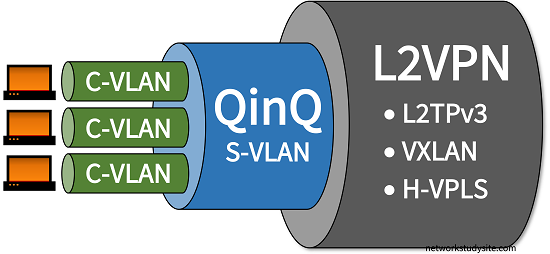
Q-in-Q is a technology that enables provider bridging by adding two VLAN tags on Ethernet frames. Such frames are assigned a hierarchy of VLAN tags and they are also called double-tagged Ethernet frames. The two VLAN tags are also referred to as a tag stack, and enable a Service Provider to assign its own Service VLAN (SVLAN) to transport traffic for one or more Customer VLAN (CVLAN). Thus, a tag stack consists of an SVLAN and a CVLAN, which are added to each Q-in-Q Ethernet frame.

Q-in-Q is part of a broader range of Service Provider technologies that enable Metro Ethernet. With Q-in-Q, the subscriber sites have a Customer Edge (CE) device which connects to a Provider Edge (PE) device. Within the provider's network Q-in-Q tunneling is used between the PE devices to connect the customer sites at OSI model Layer-2 (Data Link Layer). Q-in-Q can also be used together with other Layer-2 tunneling technologies, such as VXLAN or VPLS or L2TPv3 to improve scalability.
What is the difference between 802.1Q and Q-in-Q?
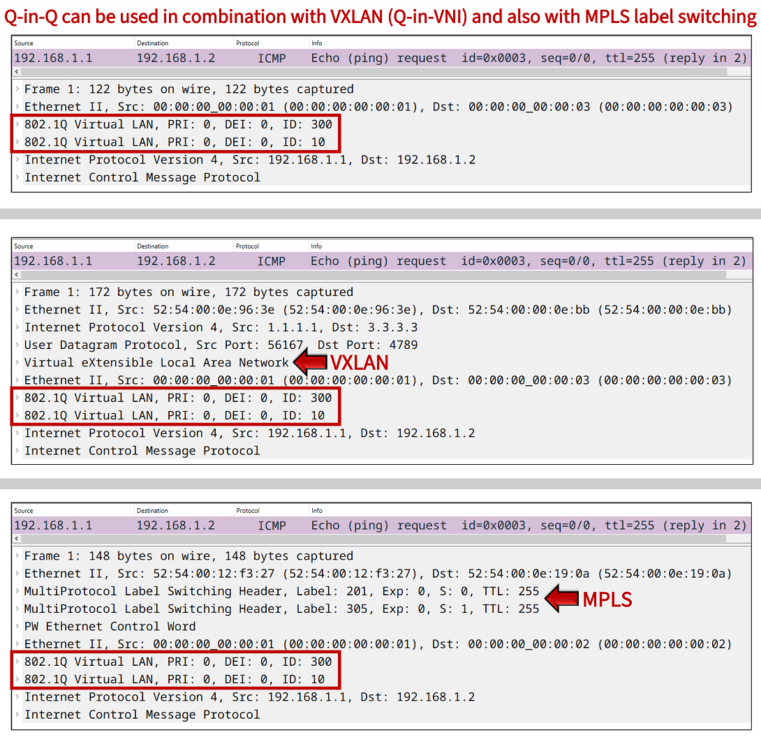
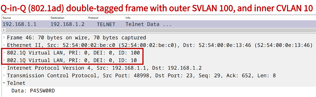
The 802.1Q network standard defines support for a 4-byte VLAN tag attached to the Ethernet frame header. Q-in-Q adds to this standard, and specifies the support for two VLAN tags attached to a single Ethernet frame header. The network standard 802.1ad defines Q-in-Q which is also known as VLAN stacking. The use of two VLAN tags enables Ethernet carrier services, an example of such an encapsulation is shown in the following packet capture.
Q-in-Q configuration with CVLAN and SVLAN
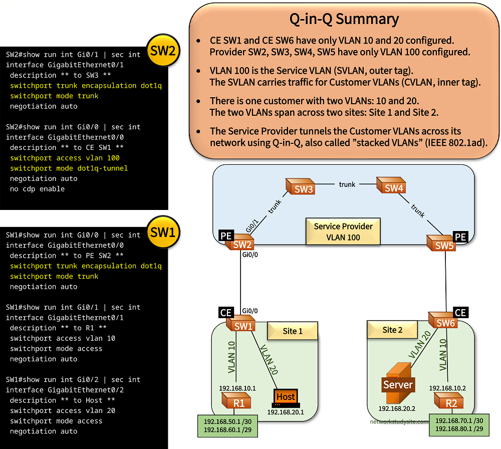
In the following sample topology there is a single customer with two sites connecting to a Service Provider (SP). The customer wishes to connect its sites at OSI Layer-2 (Data Link Layer). This is achieved with the SP's implementation of VLAN tunnelling, also called Q-in-Q.
With Q-in-Q an outer VLAN tag (the Service VLAN) is added to any VLANs received from the customer. Thus, the customer traffic has two VLAN tags attached within the SP's network, the traffic is double-tagged. This creates a tunnel through the SP's network. Below, the VLAN 100 (SVLAN) is assigned by the SP to VLAN 10 (192.168.10.0 /29) and VLAN 20 (192.168.20.0 /29) received from the customer (CVLAN).
The Provider Edge (PE) switches are the endpoints of the Q-in-Q tunnel. The Customer Edge (CE) switches have the CVLANs configured. Note that in this example the Host and Server also run Cisco IOS.
Configuration:
SW1 (CE)
SW1#show run int Gi0/0 | sec int
interface GigabitEthernet0/0
 description ** to PE SW2 **
 switchport trunk encapsulation dot1q
 switchport mode trunk
 negotiation auto

SW1#show run int Gi0/1 | sec int
interface GigabitEthernet0/1
 description ** to R1 **
 switchport access vlan 10
 switchport mode access
 negotiation auto

SW1#show run int Gi0/2 | sec int
interface GigabitEthernet0/2
 description ** to Host **
 switchport access vlan 20
 switchport mode access
 negotiation auto
SW2 (PE)
SW2#show run int Gi0/1 | sec int
interface GigabitEthernet0/1
 description ** to SW3 **
 switchport trunk encapsulation dot1q
 switchport mode trunk
 negotiation auto

SW2#show run int Gi0/0 | sec int
interface GigabitEthernet0/0
 description ** to CE SW1 **
 switchport access vlan 100
 switchport mode dot1q-tunnel
 negotiation auto
 no cdp enable
SW3
SW3#show run int Gi0/0 | sec int
interface GigabitEthernet0/0
 description ** to SW4 **
 switchport trunk encapsulation dot1q
 switchport mode trunk
 negotiation auto

SW3#show run int Gi0/1 | sec int
interface GigabitEthernet0/1
 description ** to SW2 **
 switchport trunk encapsulation dot1q
 switchport mode trunk
 negotiation auto
SW4
SW4#show run int Gi0/0 | sec int
interface GigabitEthernet0/0
 description ** to SW3 **
 switchport trunk encapsulation dot1q
 switchport mode trunk
 negotiation auto

SW4#show run int Gi0/1 | sec int
interface GigabitEthernet0/1
 description ** to SW5 **
 switchport trunk encapsulation dot1q
 switchport mode trunk
 negotiation auto
SW5 (PE)
SW5#show run int Gi0/1 | sec int
interface GigabitEthernet0/1
 description ** to SW4 **
 switchport trunk encapsulation dot1q
 switchport mode trunk
 negotiation auto

SW5#show run int Gi0/0 | sec int
interface GigabitEthernet0/0
 switchport access vlan 100
 switchport mode dot1q-tunnel
 negotiation auto
 no cdp enable
SW6 (CE)
SW6#show run int Gi0/0 | sec int
interface GigabitEthernet0/0
 description ** to PE SW5 **
 switchport trunk encapsulation dot1q
 switchport mode trunk
 negotiation auto

SW6#show run int Gi0/1 | sec int
interface GigabitEthernet0/1
 description ** to R2 **
 switchport access vlan 10
 switchport mode access
 negotiation auto

SW6#show run int Gi0/2 | sec int
interface GigabitEthernet0/2
 description ** to Server **
 switchport access vlan 20
 switchport mode access
 negotiation auto
Host#ping 192.168.20.2
Type escape sequence to abort.
Sending 5, 100-byte ICMP Echos to 192.168.20.2, timeout is 2 seconds:
!!!!!
Success rate is 100 percent (5/5), round-trip min/avg/max = 8/8/9 ms      « The Host pings the Server in the same subnet


Host#show arp
Protocol  Address          Age (min)  Hardware Addr   Type   Interface
Internet  192.168.20.1            -   5254.0011.485b  ARPA   GigabitEthernet0/2
Internet  192.168.20.2           44   5254.0009.bc08  ARPA   GigabitEthernet0/2      « The Server's MAC address is added to the ARP table on the Host


SW2#show dot1q-tunnel

dot1q-tunnel mode LAN Port(s)
-----------------------------
Gi0/0


SW2#show int trunk

Port        Mode             Encapsulation  Status        Native vlan
Gi0/1       on               802.1q         trunking      1

Port        Vlans allowed on trunk
Gi0/1       1-4094

Port        Vlans allowed and active in management domain
Gi0/1       1,100

Port        Vlans in spanning tree forwarding state and not pruned
Gi0/1       1,100


SW2#show vlan br

VLAN Name                             Status    Ports
---- -------------------------------- --------- -------------------------------
1    default                          active    Gi0/2, Gi0/3
100  Service-VLAN                     active    Gi0/0      « SW2 has only the SVLAN configured
1002 fddi-default                     act/unsup
1003 token-ring-default               act/unsup
1004 fddinet-default                  act/unsup
1005 trnet-default                    act/unsup


SW1#show int trunk

Port        Mode             Encapsulation  Status        Native vlan
Gi0/0       on               802.1q         trunking      1

Port        Vlans allowed on trunk
Gi0/0       1-4094

Port        Vlans allowed and active in management domain
Gi0/0       1,10,20

Port        Vlans in spanning tree forwarding state and not pruned
Gi0/0       1,10,20


SW3#show int trunk

Port        Mode             Encapsulation  Status        Native vlan
Gi0/0       on               802.1q         trunking      1
Gi0/1       on               802.1q         trunking      1

Port        Vlans allowed on trunk
Gi0/0       1-4094
Gi0/1       1-4094

Port        Vlans allowed and active in management domain
Gi0/0       1,100
Gi0/1       1,100

Port        Vlans in spanning tree forwarding state and not pruned
Gi0/0       1,100
Gi0/1       1,100
In this sample topology, R1 and R2 establish an OSPF neighborship through the Q-in-Q tunnel. Another routing protocol - such as BGP - could also be configured between R1 and R2 to exchange prefixes. In fact, the two routers may themselves be managed by a different Service Provider to provision another service, such as an MPLS L3VPN (with Q-in-Q Layer-2 access).
R1#show ip ospf nei

Neighbor ID     Pri   State           Dead Time   Address         Interface
2.2.2.2           1   FULL/DR         00:00:36    192.168.10.2    GigabitEthernet0/1     « OSPF neighborship established


R1#show ip route ospf | beg Ga
Gateway of last resort is not set

      192.168.70.0/30 is subnetted, 1 subnets
O        192.168.70.0 [110/2] via 192.168.10.2, 00:58:15, GigabitEthernet0/1      « Routes learned through OSPF from R2
      192.168.80.0/29 is subnetted, 1 subnets
O        192.168.80.0 [110/2] via 192.168.10.2, 00:58:15, GigabitEthernet0/1


R1#ping 192.168.70.1 source 192.168.50.1
Type escape sequence to abort.
Sending 5, 100-byte ICMP Echos to 192.168.70.1, timeout is 2 seconds:
Packet sent with a source address of 192.168.50.1
!!!!!
Success rate is 100 percent (5/5), round-trip min/avg/max = 7/7/8 ms


R1#trace 192.168.70.1 source 192.168.50.1 pr 1
Type escape sequence to abort.
Tracing the route to 192.168.70.1
VRF info: (vrf in name/id, vrf out name/id)
  1 192.168.10.2 6 msec        « From R1 to R2 there is only 1 hop (Layer 3)
The following image shows another overview of the Q-in-Q Service Provider design. Oone customer is assigned a single Service VLAN (SVLAN) within the Service Provider's network. The SVLAN carries traffic for two Customer VLANs (CVLAN) between Site 1 and Site 2.

Layer-2 Protocol Tunneling configuration
The Service Provider Q-in-Q tunnel ends on the PE devices SW2 and SW5. In the following example, the Q-in-Q tunnel is configured to transport the Layer-2 protocols CDP and LLDP.
SW2>
SW2>enable
SW2#configure terminal
Enter configuration commands, one per line.  End with CNTL/Z.
SW2(config)#interface Gi0/0
SW2(config-if)#description ** to CE SW1 **
SW2(config-if)#switchport access vlan 100
SW2(config-if)#switchport mode dot1q-tunnel
SW2(config-if)#l2protocol-tunnel cdp
SW2(config-if)#l2protocol-tunnel lldp
SW2(config-if)#
SW2(config-if)#exit
SW2(config)#
SW2(config)#exit
SW2#
This is achieved by configuring the CE-facing interface on the Q-in-Q PE switches with the command l2protocol-tunnel cdp and l2protocol-tunnel lldp. As a result, the CE devices (SW1 and SW6) form CDP and LLDP neighborships across the (transparent) Q-on-Q provider network. This is shown in the following outputs.
SW1#show cdp nei
Capability Codes: R - Router, T - Trans Bridge, B - Source Route Bridge
                  S - Switch, H - Host, I - IGMP, r - Repeater, P - Phone,
                  D - Remote, C - CVTA, M - Two-port Mac Relay

Device ID        Local Intrfce     Holdtme    Capability  Platform  Port ID
Host             Gig 0/2           147              R B             Gig 0/2
SW6              Gig 0/0           8               R S I            Gig 0/0      « The CE devices receive each others' CDP packets
R1               Gig 0/1           140              R B             Gig 0/1

Total cdp entries displayed : 3


SW1#show lldp nei
Capability codes:
    (R) Router, (B) Bridge, (T) Telephone, (C) DOCSIS Cable Device
    (W) WLAN Access Point, (P) Repeater, (S) Station, (O) Other

Device ID           Local Intf     Hold-time  Capability      Port ID
SW6                 Gi0/0          120        R               Gi0/0              « The CE devices receive each others' LLDP packets

Total entries displayed: 1
Layer-2 protocol tunneling is implemented with GBPT encapsulation. Generic Bridge PDU Tunneling (GBPT) encapsulates Layer-2 control plane protocols (such as CDP and LLDP) and uses a multicast destination MAC address. This means, when L2 Protocol Tunneling is enabled on the Q-in-Q PE switches, the destination MAC address is rewritten to the GBPT multicast address 01:00:0c:cd:cd:d0.
Accordingly, the CDP and LLDP traffic is sent through the SP core network as data traffic within VLAN 100 and using GBPT.

Native VLAN tagging
To ensure network security and to avoid certain types of misconfigurations between the customer network and the service provider network, it is advised to configure native VLAN tagging on the PE switches.
The command vlan dot1Q tag native is applied in global configuration mode. The following show command verifies that native VLAN tagging is enabled.
SW2#show vlan dot1q tag native
dot1q native vlan tagging is enabled
Configuring L2PT and EtherChannel with Q-in-Q
In this example scenario, each CE switch on Site 1 and Site 2 has multiple physical links to multiple PE switches. The physical links are bundled into a single logical Layer-2 EtherChannel which is configured on each CE switch. The Service Provider (SP) uses Q-in-Q VLAN tunneling to connect the two sites at OSI Layer-2.
Also, the SP tunnels the Layer-2 protocols received from the CE switches, such as the Link Aggregation Control Protocol (LACP). This enables EtherChannel link aggregation on CE SW1, and CE SW2.
An important aspect of the SP Q-in-Q configuration is that each physical link that connects the CE switch to the PE switches is assigned a different Service VLAN. As a result, there are four SVLANs configured in this topology. Such a redundant design improves network availability and increases overall bandwidth.

Configuration:
SW2 (PE)
SW2#show run int Gi0/1 | sec int
interface GigabitEthernet0/1
 description ** to SW3 **
 switchport trunk encapsulation dot1q
 switchport mode trunk
 negotiation auto

SW2#show run int Gi0/0 | sec int
interface GigabitEthernet0/0
 description ** to CE SW1 **
 switchport access vlan 100
 switchport mode dot1q-tunnel
 negotiation auto
 l2protocol-tunnel point-to-point pagp
 l2protocol-tunnel point-to-point lacp
 l2protocol-tunnel point-to-point udld
 no cdp enable

SW2#show run int Gi0/2 | sec int
interface GigabitEthernet0/2
 description ** to CE SW1 **
 switchport access vlan 200
 switchport mode dot1q-tunnel
 negotiation auto
 l2protocol-tunnel point-to-point pagp
 l2protocol-tunnel point-to-point lacp
 l2protocol-tunnel point-to-point udld
 no cdp enable
SW7 (PE)
SW7#show run int Gi0/2 | sec int
interface GigabitEthernet0/2
 description ** to SW3 **
 switchport trunk encapsulation dot1q
 switchport mode trunk
 negotiation auto

SW7#show run int Gi0/0 | sec int
interface GigabitEthernet0/0
 description ** to CE SW1 **
 switchport access vlan 300
 switchport mode dot1q-tunnel
 negotiation auto
 l2protocol-tunnel point-to-point pagp
 l2protocol-tunnel point-to-point lacp
 l2protocol-tunnel point-to-point udld
 no cdp enable

SW7#show run int Gi0/1 | sec int
interface GigabitEthernet0/1
 description ** to CE SW1 **
 switchport access vlan 400
 switchport mode dot1q-tunnel
 negotiation auto
 l2protocol-tunnel point-to-point pagp
 l2protocol-tunnel point-to-point lacp
 l2protocol-tunnel point-to-point udld
 no cdp enable
SW1 (CE)
SW1#show run int Gi0/0 | sec int
interface GigabitEthernet0/0
 description ** to PE SW2 **
 switchport trunk encapsulation dot1q
 switchport mode trunk
 negotiation auto
 no cdp enable
 channel-group 10 mode active

SW1#show run int Gi0/3 | sec int
interface GigabitEthernet0/3
 description ** to PE SW2 **
 switchport trunk encapsulation dot1q
 switchport mode trunk
 negotiation auto
 no cdp enable
 channel-group 10 mode active

SW1#show run int Gi1/0 | sec int
interface GigabitEthernet1/0
 description ** to PE SW7 **
 switchport trunk encapsulation dot1q
 switchport mode trunk
 negotiation auto
 no cdp enable
 channel-group 10 mode active

SW1#show run int Gi1/1 | sec int
interface GigabitEthernet1/1
 description ** to PE SW7 **
 switchport trunk encapsulation dot1q
 switchport mode trunk
 negotiation auto
 no cdp enable
 channel-group 10 mode active

SW1#show run int Po10 | sec int
interface Port-channel10
 description ** EtherChannel to PE Switches **
 switchport trunk encapsulation dot1q
 switchport mode trunk

SW1#show run int Gi0/1 | sec int
interface GigabitEthernet0/1
 description ** to R1 **
 switchport access vlan 10
 switchport mode access
 negotiation auto
 no cdp enable

SW1#show run int Gi0/2 | sec int
interface GigabitEthernet0/2
 description ** to Host **
 switchport access vlan 20
 switchport mode access
 negotiation auto
 no cdp enable
SW3
SW3#show run int Gi0/1 | sec int
interface GigabitEthernet0/1
 description ** to SW2 **
 switchport trunk encapsulation dot1q
 switchport mode trunk
 negotiation auto

SW3#show run int Gi0/0 | sec int
interface GigabitEthernet0/0
 description ** to SW4 **
 switchport trunk encapsulation dot1q
 switchport mode trunk
 negotiation auto
SW2#show dot1q-tunnel

dot1q-tunnel mode LAN Port(s)
-----------------------------
Gi0/0
Gi0/2


SW2#show l2protocol-tunnel
COS for Encapsulated Packets: 5
Drop Threshold for Encapsulated Packets: 0

Port                Protocol    Shutdown  Drop      Encaps    Decaps    Drop
                                Threshold Threshold Counter   Counter   Counter
------------------- ----------- --------- --------- --------- --------- ---------
Gi0/0               ---           ----      ----         ----      ----      ----
                    ---           ----      ----         ----      ----      ----
                    ---           ----      ----         ----      ----      ----
                    ---           ----      ----         ----      ----      ----
                    pagp          ----      ----            0         0         0
                    lacp          ----      ----          484       615         0       « Layer-2 LACP traffic visible
                    udld          ----      ----            0         0         0
Gi0/2               ---           ----      ----         ----      ----      ----
                    ---           ----      ----         ----      ----      ----
                    ---           ----      ----         ----      ----      ----
                    ---           ----      ----         ----      ----      ----
                    pagp          ----      ----            0         0         0
                    lacp          ----      ----          484       536         0
                    udld          ----      ----            0         0         0


SW1#show etherchannel summary
Flags:  D - down        P - bundled in port-channel
        I - stand-alone s - suspended
        H - Hot-standby (LACP only)
        R - Layer3      S - Layer2
        U - in use      N - not in use, no aggregation
        f - failed to allocate aggregator

        M - not in use, minimum links not met
        m - not in use, port not aggregated due to minimum links not met
        u - unsuitable for bundling
        w - waiting to be aggregated
        d - default port

        A - formed by Auto LAG


Number of channel-groups in use: 1
Number of aggregators:           1

Group  Port-channel  Protocol    Ports
------+-------------+-----------+-----------------------------------------------
10     Po10(SU)        LACP      Gi0/0(P)    Gi0/3(P)    Gi1/0(P)             « Layer-2 LACP etherchannel bundled and in use
                                 Gi1/1(P)


SW1#show etherchannel
                Channel-group listing:
                ----------------------

Group: 10
----------
Group state = L2
Ports: 4   Maxports = 4           « Four ports are bundled
Port-channels: 1 Max Port-channels = 4
Protocol:   LACP
Minimum Links: 0


R1#ping 192.168.10.2
Type escape sequence to abort.
Sending 5, 100-byte ICMP Echos to 192.168.10.2, timeout is 2 seconds:
!!!!!
Success rate is 100 percent (5/5), round-trip min/avg/max = 8/8/10 ms


Host#ping 192.168.20.2
Type escape sequence to abort.
Sending 5, 100-byte ICMP Echos to 192.168.20.2, timeout is 2 seconds:
!!!!!
Success rate is 100 percent (5/5), round-trip min/avg/max = 8/9/12 ms
On the Service Provider switches, all SVLANs are configured, and allowed on the trunk links connecting the switches to each other.
SW3#show vlan br

VLAN Name                             Status    Ports
---- -------------------------------- --------- -------------------------------
1    default                          active    Gi0/3
100  Service-VLAN1                    active
200  Service-VLAN2                    active
300  Service-VLAN3                    active
400  Service-VLAN4                    active
1002 fddi-default                     act/unsup
1003 token-ring-default               act/unsup
1004 fddinet-default                  act/unsup
1005 trnet-default                    act/unsup


SW3#show int trunk

Port        Mode             Encapsulation  Status        Native vlan
Gi0/0       on               802.1q         trunking      1
Gi0/1       on               802.1q         trunking      1
Gi0/2       auto             n-802.1q       trunking      1

Port        Vlans allowed on trunk
Gi0/0       1-4094
Gi0/1       1-4094
Gi0/2       1-4094

Port        Vlans allowed and active in management domain
Gi0/0       1,100,200,300,400
Gi0/1       1,100,200,300,400
Gi0/2       1,100,200,300,400

Port        Vlans in spanning tree forwarding state and not pruned
Gi0/0       1,100,200,300,400
Gi0/1       1,100,200,300,400
Gi0/2       1,100,200,300,400
Provider switches learn duplicate MAC addresses with Independent VLAN Learning (IVL)
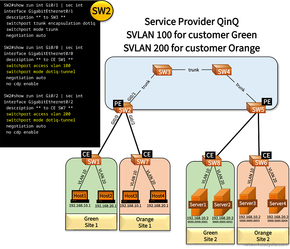
In this example, two customers (Green and Orange) are connected to the SP. With Q-in-Q, the SP connects two sites for each customer at the OSI Layer-2 Data Link Layer. Each customer uses the same VLANs (10 and 20). These customer VLANs (CVLAN) coexist separately and independently due to different Service VLANs (SVLAN 100 and 200) assigned by the SP within the Q-in-Q core network.
Thus, customer Green has SVLAN 100 assigned, and customer Orange has SVLAN 200 assigned. An important aspect of Q-in-Q is that the switches within the SP's core learn all of the MAC addresses belonging to each customer's network. This means that SW2, SW3, SW4, and SW5 learn the MAC addresses of each Host and Server in this topology, altogether 8 MAC addresses.
Configuration:
SW2 (PE)
SW2#show run int Gi0/1 | sec int
interface GigabitEthernet0/1
 description ** to SW3 **
 switchport trunk encapsulation dot1q
 switchport mode trunk
 negotiation auto

SW2#show run int Gi0/0 | sec int
interface GigabitEthernet0/0
 description ** to CE SW1 **
 switchport access vlan 100
 switchport mode dot1q-tunnel
 negotiation auto
 no cdp enable

SW2#show run int Gi0/2 | sec int
interface GigabitEthernet0/2
 description ** to CE SW7 **
 switchport access vlan 200
 switchport mode dot1q-tunnel
 negotiation auto
 no cdp enable
SW5 (PE)
SW5#show run int Gi0/1 | sec int
interface GigabitEthernet0/1
 description ** to SW4 **
 switchport trunk encapsulation dot1q
 switchport mode trunk
 negotiation auto

SW5#show run int Gi0/0 | sec int
interface GigabitEthernet0/0
 description ** to CE SW6 **
 switchport access vlan 200
 switchport mode dot1q-tunnel
 negotiation auto
 no cdp enable

SW5#show run int Gi0/2 | sec int
interface GigabitEthernet0/2
 description ** to CE SW8 **
 switchport access vlan 100
 switchport mode dot1q-tunnel
 negotiation auto
 no cdp enable
SW3
SW3#show run int Gi0/0 | sec int
interface GigabitEthernet0/0
 description ** to SW4 **
 switchport trunk encapsulation dot1q
 switchport mode trunk
 negotiation auto

SW3#show run int Gi0/1 | sec int
interface GigabitEthernet0/1
 description ** to SW2 **
 switchport trunk encapsulation dot1q
 switchport mode trunk
 negotiation auto
SW1 (CE)
SW1#show run int Gi0/0 | sec int
interface GigabitEthernet0/0
 description ** to PE SW2 **
 switchport trunk encapsulation dot1q
 switchport mode trunk
 negotiation auto

SW1#show run int Gi0/1 | sec int
interface GigabitEthernet0/1
 description ** to Host1 **
 switchport access vlan 10
 switchport mode access
 negotiation auto

SW1#show run int Gi0/2 | sec int
interface GigabitEthernet0/2
 description ** to Host2 **
 switchport access vlan 20
 switchport mode access
 negotiation auto
SW7 (CE)
SW7#show run int Gi0/2 | sec int
interface GigabitEthernet0/2
 description ** to PE SW2 **
 switchport trunk encapsulation dot1q
 switchport mode trunk
 negotiation auto

SW7#show run int Gi0/0 | sec int
interface GigabitEthernet0/0
 description ** to Host3 **
 switchport access vlan 10
 switchport mode access
 negotiation auto

SW7#show run int Gi0/1 | sec int
interface GigabitEthernet0/1
 description ** to Host4 **
 switchport access vlan 20
 switchport mode access
 negotiation auto
SW3#show mac address-table
          Mac Address Table
-------------------------------------------

Vlan    Mac Address       Type        Ports
----    -----------       --------    -----
   1    5254.000b.cdd5    DYNAMIC     Gi0/0
 100    0000.0000.0001    DYNAMIC     Gi0/0     « Server1 MAC address
 100    0000.0000.0002    DYNAMIC     Gi0/0     « Server2 MAC address
 100    0000.0000.000a    DYNAMIC     Gi0/1
 100    0000.0000.000b    DYNAMIC     Gi0/1
 200    0000.0000.0003    DYNAMIC     Gi0/0     « Server3 MAC address
 200    0000.0000.0004    DYNAMIC     Gi0/0     « Server4 MAC address
 200    0000.0000.000c    DYNAMIC     Gi0/1
 200    0000.0000.000d    DYNAMIC     Gi0/1
Total Mac Addresses for this criterion: 9


Host1#ping 192.168.10.2
Type escape sequence to abort.
Sending 5, 100-byte ICMP Echos to 192.168.10.2, timeout is 2 seconds:
!!!!!
Success rate is 100 percent (5/5), round-trip min/avg/max = 7/9/12 ms


Host1#show arp
Protocol  Address          Age (min)  Hardware Addr   Type   Interface
Internet  192.168.10.1            -   0000.0000.000a  ARPA   GigabitEthernet0/1    « Host1 MAC address
Internet  192.168.10.2            2   0000.0000.0001  ARPA   GigabitEthernet0/1    « Server1 MAC address


SW2#show mac address-table
          Mac Address Table
-------------------------------------------

Vlan    Mac Address       Type        Ports
----    -----------       --------    -----
   1    5254.001a.e344    DYNAMIC     Gi0/1
 100    0000.0000.0001    DYNAMIC     Gi0/1
 100    0000.0000.0002    DYNAMIC     Gi0/1
 100    0000.0000.000a    DYNAMIC     Gi0/0
 100    0000.0000.000b    DYNAMIC     Gi0/0
 100    5254.0002.9036    DYNAMIC     Gi0/0   « CE SW1 MAC address
 100    5254.001a.e344    DYNAMIC     Gi0/1
 200    0000.0000.0003    DYNAMIC     Gi0/1
 200    0000.0000.0004    DYNAMIC     Gi0/1
 200    0000.0000.000c    DYNAMIC     Gi0/2
 200    0000.0000.000d    DYNAMIC     Gi0/2
 200    5254.0009.3224    DYNAMIC     Gi0/2   « CE SW7 MAC address
 200    5254.001a.e344    DYNAMIC     Gi0/1
Total Mac Addresses for this criterion: 13


SW2#show dot1q-tunnel

dot1q-tunnel mode LAN Port(s)
-----------------------------
Gi0/0
Gi0/2


SW5#show dot1q-tunnel

dot1q-tunnel mode LAN Port(s)
-----------------------------
Gi0/0
Gi0/2
As the VLANs are separated within the SP's network, this also means separation of Layer-3 information. In other words, the customers can use overlapping IP addresses due to the virtual segmentation of customer networks by Q-in-Q. The following image shows an overview of the design implemented in this example scenario, and the separation of VLANs.

If Shared VLAN Learning (SVL) is used by the SP switches, it means that duplicate MAC addresses between two customers can cause network issues. For example, if Green and Orange each had a Host with the same MAC address, the SP switches would learn a single (shared) MAC address entry representing the two Hosts, potentially restricting access to one of the Hosts.
However, if Independent VLAN Learning (IVL) is used by the SP switches, it means that MAC addresses are separated based on the SVLAN. Therefore, a MAC address only needs to be unique in each independent customer network or in each SVLAN. As a result, different customers (different SVLANs) can have overlapping MAC addresses.
In this example scenario, the SP switches use IVL. As seen below, each customer MAC address is assigned to a specific SVLAN (100 or 200).
SW2#show mac address-table
          Mac Address Table
-------------------------------------------

Vlan    Mac Address       Type        Ports
----    -----------       --------    -----
   1    5254.001a.e344    DYNAMIC     Gi0/1
 100    0000.0000.0001    DYNAMIC     Gi0/1     « Server1 MAC address in SVLAN 100
 100    0000.0000.0002    DYNAMIC     Gi0/1
 100    0000.0000.000a    DYNAMIC     Gi0/0
 100    0000.0000.000b    DYNAMIC     Gi0/0
 100    5254.0002.9036    DYNAMIC     Gi0/0
 100    5254.001a.e344    DYNAMIC     Gi0/1
 200    0000.0000.0003    DYNAMIC     Gi0/1
 200    0000.0000.0004    DYNAMIC     Gi0/1
 200    0000.0000.000c    DYNAMIC     Gi0/2     « Host3 MAC address in SVLAN 200
 200    0000.0000.000d    DYNAMIC     Gi0/2
 200    5254.0009.3224    DYNAMIC     Gi0/2
 200    5254.001a.e344    DYNAMIC     Gi0/1
Total Mac Addresses for this criterion: 13
However, in the next example scenario Host3 (customer Orange) is configured with the same MAC address as Server1 (customer Green). As a result, the SP switches learn the same MAC address 0000.0000.0001 on two different interfaces.
Due to IVL this does not cause a problem as these MAC addresses are assigned to different SVLANs. The following output shows how identical MAC addresses learned from two different interfaces are separated by the SVLAN identifier.
SW3#show mac address-table
          Mac Address Table
-------------------------------------------

Vlan    Mac Address       Type        Ports
----    -----------       --------    -----
   1    5254.000b.cdd5    DYNAMIC     Gi0/0
   1    5254.0013.38fb    DYNAMIC     Gi0/1
 100    0000.0000.0001    DYNAMIC     Gi0/0
 100    0000.0000.0002    DYNAMIC     Gi0/0
 100    0000.0000.000a    DYNAMIC     Gi0/1
 100    0000.0000.000b    DYNAMIC     Gi0/1
 200    0000.0000.0001    DYNAMIC     Gi0/1
 200    0000.0000.0003    DYNAMIC     Gi0/0
 200    0000.0000.000c    DYNAMIC     Gi0/1
Total Mac Addresses for this criterion: 9