Network Time Protocol (NTP) Cisco Router Configuration
Table of Contents
Jump to section:
- • What is Network Time Protocol?
- • What is NTP stratum?
- • Difference between NTP v3 and v4
- • How to configure NTP?
- • NTP with authentication
- • NTP master command
- • NTP with access-list
- • NTP peers
- • NTP broadcast
- • NTP multicast
- • NTP with IPv6
- • Maximum associations
- • What is the difference between the hardware clock and the system clock?
- • Download section
- What is Network Time Protocol? ‹
- What is NTP stratum? ‹
- Difference between NTP v3 and v4 ‹
- How to configure NTP? ‹
- NTP with authentication ‹
- NTP master command ‹
- NTP with access-list ‹
- NTP peers ‹
- NTP broadcast ‹
- NTP multicast ‹
- NTP with IPv6 ‹
- Maximum associations ‹
- What is the difference between the hardware clock and the system clock? ‹
- Download section ‹
What is Network Time Protocol?
Network Time Protocol (NTP) is one of the oldest protocols on the internet and provides a mechanism of time synchronization for computers over UDP port 123. NTP provides time synchronization through a hierarchical system of public and private servers. NTP uses the Coordinated Universal Time (UTC) time standard as a reference and can synchronize network devices with high levels of accuracy (deviation of milliseconds).

Many system functions rely on NTP. For example, certificate based authentication relies on an accurate and common time source to verify a Certificate Revocation List (CRL). Also, network monitoring systems rely on clock synchronization to provide valid timestamps for event logs.
What is NTP stratum?
Each NTP Server has a stratum number assigned, and NTP packets contain the stratum number of the device that originated (sent) the packet. The stratum number is encoded in an 8-bit (1 byte) field, which provides 255 possible values. However, when looking at a packet capture only the values 0 - 15 are ever used. The values represent a hierarchical system of time source accuracy described in the following table.
| Value | Description |
|---|---|
| 0 | When an NTP client sends its first polling messages to an NTP server, the stratum number 0 will be set, and indicates an invalid stratum level. |
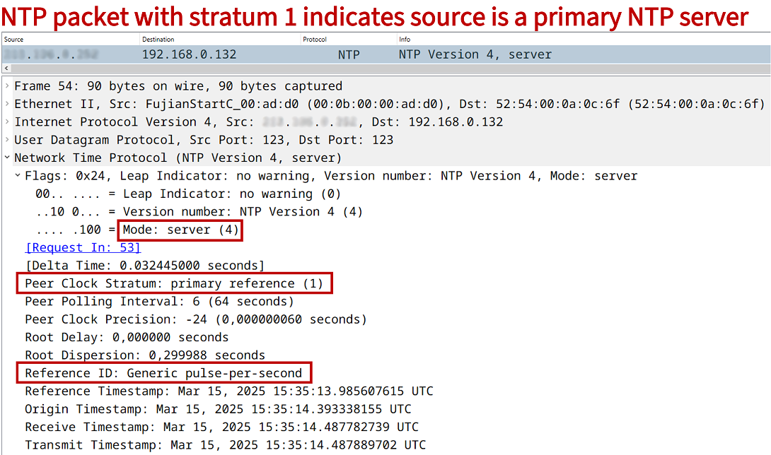
| 1 | These are called primary NTP servers with a very high level of time accuracy, and form the backbone of the NTP stratum hierarchy. Primary NTP servers usually synchronize with a GPS clock or an atomic clock (cesium oscillator). An NTP packet sent from a primary NTP server may contain the stratum 1 reference information "Generic pulse-per-second" to indicate its high-precision time source. |
| 2 - 15 | These are called secondary NTP servers. A higher/larger stratum number indicates a lower level of time accuracy. A stratum level 2 NTP server directly synchronizes its time with a primary server. |
| 16 | This indicates an unsynchronized time source. |
Regarding secondary NTP servers, the following outputs from R1 indicate that it is a stratum 4 NTP time source, because it has synchronized its time with a stratum 3 time source located at the IP address 10.0.0.2. We also find out from the output of show ntp associations that the NTP server at 10.0.0.2 gets its own time source from a time server located at 192.168.1.20.
R1#show ntp status
Clock is synchronized, stratum 4, reference is 10.0.0.2
nominal freq is 1000.0003 Hz, actual freq is 999.5412 Hz, precision is 2**17
ntp uptime is 1172400 (1/100 of seconds), resolution is 1001
reference time is EB802001.43994AFA (15:49:21.264 UTC Sat Mar 15 2025)
clock offset is -148.8266 msec, root delay is 35.15 msec
root dispersion is 308.81 msec, peer dispersion is 6.66 msec
loopfilter state is 'SPIK' (Spike), drift is 0.000459016 s/s
system poll interval is 64, last update was 752 sec ago.


R1#show ntp associations

  address         ref clock       st   when   poll reach  delay  offset   disp
 ~10.0.0.2        192.168.1.20     3     77     64     1  0.866 -66.794 7937.5
 * sys.peer, # selected, + candidate, - outlyer, x falseticker, ~ configured
The stratum hierarchy level is described in detail in the RFC 5905. A quote from the RFC is displayed below.
Loosely following the conventions established by the telephone industry, the level of each server in the hierarchy is defined by a stratum number. Primary servers are assigned stratum one; secondary servers at each lower level are assigned stratum numbers one greater than the preceding level. As the stratum number increases, its accuracy degrades depending on the particular network path and system clock stability.
RFC 5905, Network Time Protocol Version 4: Protocol and Algorithms Specification
Difference between NTP v3 and v4
NTP version 4 is the latest specification standardized in RFC 5905, and it supports time synchronization over the IPv6 address-family. Remember that IPv6 does not use broadcast, so in order to optimize network resource utilization in a LAN segment, NTPv4 IPv6 multicast mode can be used.
NTPv4 also adds the option for Public Key Infrastructure (PKI) authentication which is detailed in RFC 5906. Note that NTPv3 supports symmetric key (password) authentication, which is still available in NTPv4. Many other improvements are also added in NTPv4 which are detailed in the RFC.
How to configure NTP?
In the following example scenario, NTP is configured in Site 1 on two devices. R1 is an NTP client and synchronizes time with the site-local stratum 3 NTP Server. In turn, the Site 1 NTP Server synchronizes its own time with the public stratum 2 NTP server. The global configuration command ntp server 10.0.0.2 is issued on R1, and the command ntp server pool.ntp.org is issued on the Site 1 NTP Server.

Configuration:
R1
R1>
R1>enable
R1#configure terminal
Enter configuration commands, one per line.  End with CNTL/Z.
R1(config)#
R1(config)#ntp server 10.0.0.2
R1(config)#
R1(config)#exit
R1#
NTP Server in Site 1
NTP-Server>
NTP-Server>enable
NTP-Server#configure terminal
Enter configuration commands, one per line.  End with CNTL/Z.
NTP-Server(config)#
NTP-Server(config)#ip domain-lookup
NTP-Server(config)#
NTP-Server(config)#ntp server pool.ntp.org
NTP-Server(config)#
NTP-Server(config)#exit
NTP-Server#exit
R1#show ntp status
Clock is synchronized, stratum 4, reference is 10.0.0.2
nominal freq is 1000.0003 Hz, actual freq is 999.5412 Hz, precision is 2**17
ntp uptime is 1172400 (1/100 of seconds), resolution is 1001
reference time is EB802001.43994AFA (15:49:21.264 UTC Sat Mar 15 2025)
clock offset is -148.8266 msec, root delay is 35.15 msec
root dispersion is 308.81 msec, peer dispersion is 6.66 msec
loopfilter state is 'SPIK' (Spike), drift is 0.000459016 s/s
system poll interval is 64, last update was 752 sec ago.
NTP with authentication
In the following example scenario, NTP authentication is configured between R1 (NTP Client) and the Site 1 local NTP Server. Note that there is no authentication configured between R2 and the NTP Server. And neither is there authentication between the Site 1 NTP Server and the public NTP Server at pool.ntp.org.
An NTP authentication-key is configured on R1 and on the Site 1 local NTP Server. This includes a key number and a key string, in this example number 100 with key P4SSW0RD. Then, the global configuration command ntp trusted-key 100 is issued on both devices.
Next, the following two commands are necessary on the NTP Client R1:
The command ntp authenticate enables time source authentication. This command is only configured on the NTP Client R1, and it is not configured on the NTP Server. The CLI help feature provides the following concise description of the command.
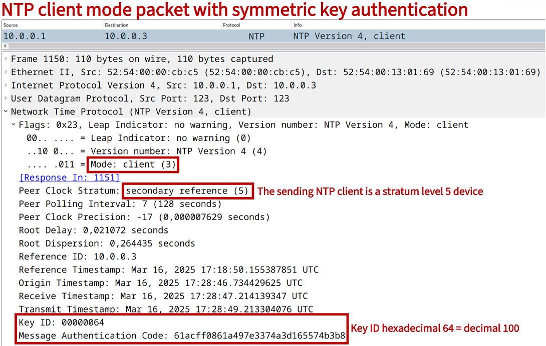
R1(config)#ntp ? access-group Control NTP access allow Allow processing of packets authenticate Authenticate time sources authentication-key Authentication key for trusted time sources broadcastdelay Estimated round-trip delay clock-period Length of hardware clock tick leap-handle To handle the leap seconds logging Enable NTP message logging master Act as NTP master clock max-associations Set maximum number of associations maxdistance Maximum Distance for synchronization mindistance Minimum distance to consider for clockhop orphan Threshold Stratum for orphan mode panic Reject time updates > panic threshold (default 1000Sec) passive NTP passive mode peer Configure NTP peer server Configure NTP server source Configure interface for source address trusted-key Key numbers for trusted time sources update-calendar Periodically update calendar with NTP time- The command ntp server 10.0.0.3 key 100 is issued on the NTP Client R1, and it configures the key to be used when polling the NTP Server. This means, the NTP Client R1 will include the authentication key in NTP packets.

Configuration:
R1
R1>
R1>enable
R1#configure terminal
Enter configuration commands, one per line.  End with CNTL/Z.
R1(config)#
R1(config)#ntp authentication-key 100 md5 P4SSW0RD
R1(config)#ntp authenticate
R1(config)#ntp trusted-key 100
R1(config)#ntp server 10.0.0.3 key 100
R1(config)#
R1(config)#exit
R1#
R1#show run | section ^ntp
ntp authentication-key 100 md5 06365B127F79592B21 7
ntp authenticate
ntp trusted-key 100
ntp server 10.0.0.3 key 100
R1#
R1#
R2
R2>
R2>enable
R2#configure terminal
Enter configuration commands, one per line.  End with CNTL/Z.
R2(config)#
R2(config)#ntp server 10.0.0.3
R2(config)#
R2(config)#exit
R2#
NTP Server Site 1
NTP-Server>
NTP-Server>enable
NTP-Server#configure terminal
Enter configuration commands, one per line.  End with CNTL/Z.
NTP-Server(config)#
NTP-Server(config)#ntp authentication-key 100 md5 P4SSW0RD
NTP-Server(config)#ntp trusted-key 100
NTP-Server(config)#ntp server pool.ntp.org
NTP-Server(config)#
NTP-Server(config)#exit
NTP-Server#
R1#show ntp associations detail
10.0.0.3 configured, ipv4, authenticated, our_master, sane, valid, stratum 4          « R1 is authenticated with the local NTP Server
ref ID 192.168.0.1 , time EB8192CD.AD90BC03 (18:11:25.677 UTC Sun Mar 16 2025)
our mode client, peer mode server, our poll intvl 64, peer poll intvl 64
root delay 20.20 msec, root disp 248.39, reach 377, sync dist 282.20
delay 0.49 msec, offset -0.6933 msec, dispersion 3.44, jitter 18.59 msec
precision 2**17, version 4
assoc id 65432, assoc name 10.0.0.3
assoc in packets 120, assoc out packets 120, assoc error packets 1
org time 00000000.00000000 (00:00:00.000 UTC Mon Jan 1 1900)
rec time EB8194D9.64F21A9A (18:20:09.394 UTC Sun Mar 16 2025)
xmt time EB8194D9.64F21A9A (18:20:09.394 UTC Sun Mar 16 2025)
filtdelay =     1.63    0.50    0.49    1.53    0.67    1.65    0.72    0.68
filtoffset =  -35.58  -18.04   -0.69   12.36   25.57   -3.36    3.33    3.50
filterror =     0.01    1.45    2.89    4.33    5.77    7.21    8.65    8.67
minpoll = 6, maxpoll = 10


R1#show ntp status
Clock is synchronized, stratum 5, reference is 10.0.0.3                               « R1 has synchronized its time with the NTP Server
nominal freq is 1000.0003 Hz, actual freq is 999.8479 Hz, precision is 2**17
ntp uptime is 704300 (1/100 of seconds), resolution is 1001
reference time is EB819419.66984366 (18:16:57.400 UTC Sun Mar 16 2025)
clock offset is -0.6933 msec, root delay is 20.69 msec
root dispersion is 265.16 msec, peer dispersion is 4.65 msec
loopfilter state is 'CTRL' (Normal Controlled Loop), drift is 0.000152382 s/s
system poll interval is 64, last update was 313 sec ago.


R2#show ntp association detail
10.0.0.3 configured, ipv4, our_master, sane, valid, stratum 4
ref ID 192.168.0.1 , time EB8194FE.B064B29B (18:20:46.689 UTC Sun Mar 16 2025)
our mode client, peer mode server, our poll intvl 64, peer poll intvl 64
root delay 19.62 msec, root disp 151.65, reach 377, sync dist 261.47
delay 0.63 msec, offset -8.3970 msec, dispersion 4.35, jitter 94.75 msec
precision 2**17, version 4
assoc id 20845, assoc name 10.0.0.3
assoc in packets 139, assoc out packets 139, assoc error packets 2
org time 00000000.00000000 (00:00:00.000 UTC Mon Jan 1 1900)
rec time EB819543.1D16D821 (18:21:55.113 UTC Sun Mar 16 2025)
xmt time EB819543.1D16D821 (18:21:55.113 UTC Sun Mar 16 2025)
filtdelay =     1.56    1.61    1.49    1.59    1.69    1.56    0.63    1.63
filtoffset =  190.68  124.98   62.50  -24.34  -18.45  -13.95   -8.39  -10.25
filterror =     0.01    1.03    2.02    3.01    4.03    5.05    6.06    7.06
minpoll = 6, maxpoll = 10


R2#show ntp status
Clock is synchronized, stratum 5, reference is 10.0.0.3                               « R2 has also synchronized its time but without authentication
nominal freq is 1000.0003 Hz, actual freq is 999.9394 Hz, precision is 2**17
ntp uptime is 827900 (1/100 of seconds), resolution is 1001
reference time is EB8193AF.E6BB3843 (18:15:11.901 UTC Sun Mar 16 2025)
clock offset is -8.3970 msec, root delay is 20.84 msec
root dispersion is 273.81 msec, peer dispersion is 4.35 msec
loopfilter state is 'CTRL' (Normal Controlled Loop), drift is 0.000060890 s/s
system poll interval is 64, last update was 455 sec ago.
NTP master command
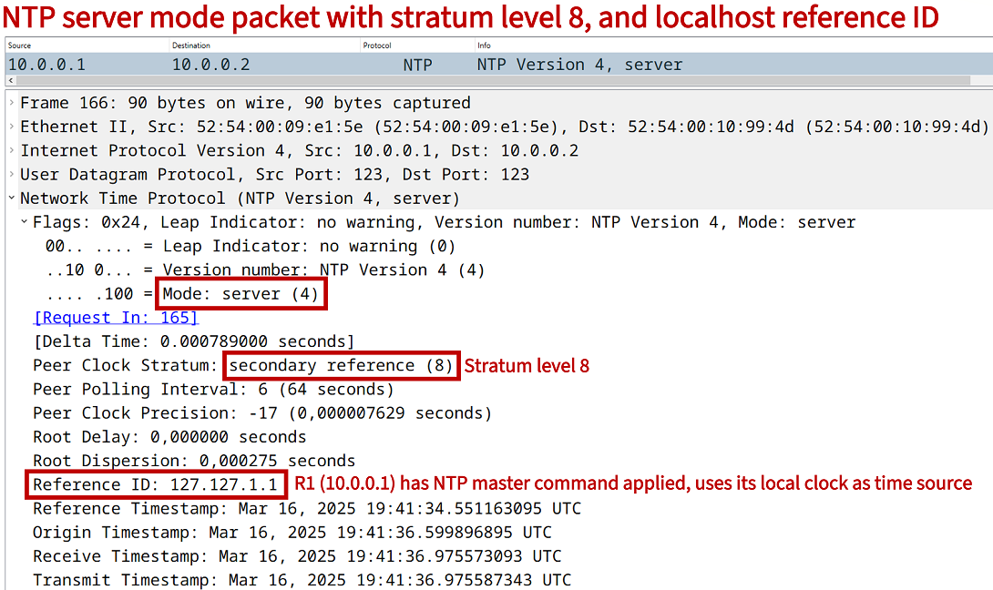
When issuing the global configuration mode command ntp master, the local device considers its own clock as an authoritative NTP time source. By default, it sets the stratum level 8, and will respond to NTP client mode packets with its own current time. The NTP master stratum level can also be statically configured.
A device configured with the ntp master command will become a time source even if it does not itself have an accurate time source (even without synchronizing to a public authoritative NTP server). In the following example configuration, R1 is configured as a time server.
R1>
R1>enable
R1#configure terminal
Enter configuration commands, one per line.  End with CNTL/Z.
R1(config)#
R1(config)#ntp master
R1(config)#
R1(config)#exit
R1#
R1#
R1#show ntp status
Clock is synchronized, stratum 8, reference is 127.127.1.1
nominal freq is 1000.0003 Hz, actual freq is 1000.0003 Hz, precision is 2**17
ntp uptime is 1300 (1/100 of seconds), resolution is 1000
reference time is EB81A6DE.8D04CDEF (19:37:02.550 UTC Sun Mar 16 2025)
clock offset is 0.0000 msec, root delay is 0.00 msec
root dispersion is 7937.70 msec, peer dispersion is 7937.50 msec
loopfilter state is 'CTRL' (Normal Controlled Loop), drift is 0.000000000 s/s
system poll interval is 16, last update was 13 sec ago.
R1#
As visible in the above output from the NTP server R1, it has the stratum level set to 8, and its clock source reference is the localhost address 127.127.1.1 (pointing to itself). When the NTP client R2 polls R1 for the current time, the following reply packet is received.
NTP with access-list
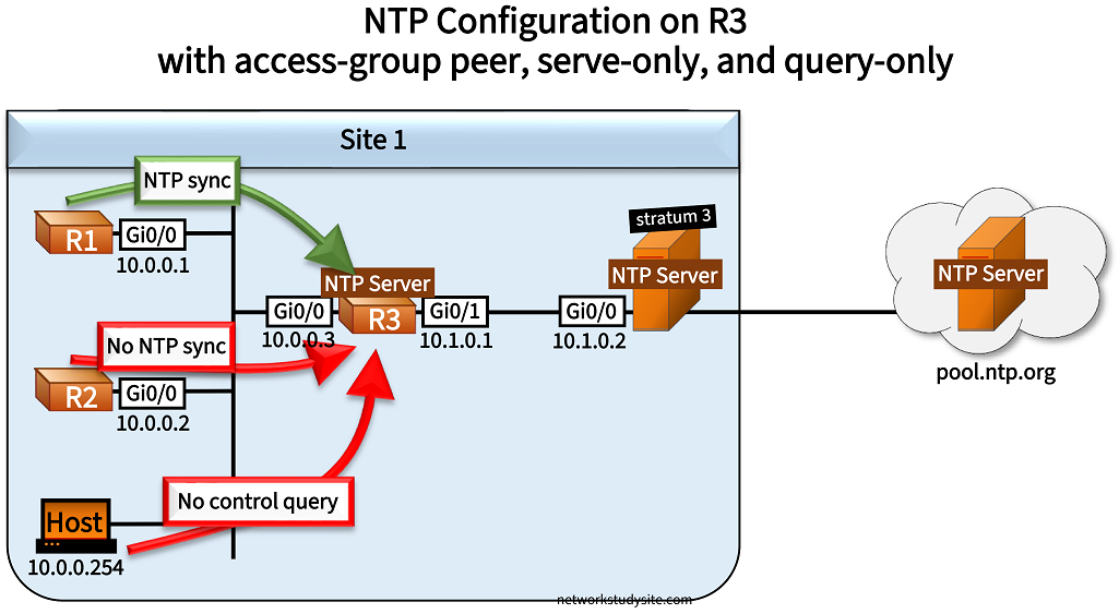
In the following example scenario, NTP is configured on R3 with multiple access-lists. R3 receives its time from the stratum 3 NTP Server in Site 1, which in turn polls the public time servers at pool.ntp.org. Three rules are applied on R3 to NTP, each rule is enforced by a standard ACL.
The command ntp access-group peer EXAMPLE-ACL2 enables NTP to receive its time information from only the stratum 3 NTP Server in Site 1. In other words, R3 is only allowed to synchronize time with a single device permitted in the EXAMPLE-ACL2.
- The command ntp access-group serve-only EXAMPLE-ACL3 allows NTP client mode packets only from R1 (IP address in EXAMPLE-ACL3). In other words, R3 only accepts time synchronization requests from R1, so R3 will only ever be an NTP Server for R1.
- The command ntp access-group query-only EXAMPLE-ACL1 denies NTP control query messages from any device. In many networks today NTP control/query messages are considered a security risk, and are either disabled completely or denied with an ACL as shown in this example. The details of control messages are described in an Informational RFC.
Configuration:
R3
R3>
R3>enable
R3#configure terminal
Enter configuration commands, one per line.  End with CNTL/Z.
R3(config)#
R3(config)#ip access-list standard EXAMPLE-ACL1
R3(config-std-nacl)#remark ** This ACL will block any NTP control/query messages **
R3(config-std-nacl)#deny any
R3(config-std-nacl)#
R3(config-std-nacl)#exit
R3(config)#
R3(config)#
R3(config)#ip access-list standard EXAMPLE-ACL2
R3(config-std-nacl)#remark ** This ACL will allow R3 to request the time from Site 1 stratum 3 NTP Server **
R3(config-std-nacl)#permit 10.1.0.2
R3(config-std-nacl)#
R3(config-std-nacl)#exit
R3(config)#
R3(config)#
R3(config)#ip access-list standard EXAMPLE-ACL3
R3(config-std-nacl)#remark ** This ACL will allow only R1 to request the time from R3 **
R3(config-std-nacl)#permit 10.0.0.1
R3(config-std-nacl)#
R3(config-std-nacl)#exit
R3(config)#
R3(config)#
R3(config)#ntp access-group query-only EXAMPLE-ACL1
R3(config)#ntp access-group peer EXAMPLE-ACL2
R3(config)#ntp access-group serve-only EXAMPLE-ACL3
R3(config)#ntp server 10.1.0.2
R3(config)#
R3(config)#exit
R3#
R3#show run | section ^ntp
ntp access-group peer EXAMPLE-ACL2
ntp access-group serve-only EXAMPLE-ACL3
ntp access-group query-only EXAMPLE-ACL1
ntp server 10.1.0.2
R3#
R2
R2>
R2>enable
R2#configure terminal
Enter configuration commands, one per line.  End with CNTL/Z.
R2(config)#
R2(config)#ntp server 10.0.0.3
R2(config)#
R2(config)#exit
R2#
R1
R1>
R1>enable
R1#configure terminal
Enter configuration commands, one per line.  End with CNTL/Z.
R1(config)#
R1(config)#ntp server 10.0.0.3
R1(config)#
R1(config)#exit
R1#
NTP Server (stratum 3)
NTP-Server>
NTP-Server>enable
NTP-Server#configure terminal
Enter configuration commands, one per line.  End with CNTL/Z.
NTP-Server(config)#
NTP-Server(config)#ntp server 1.europe.pool.ntp.org
NTP-Server(config)#ntp server 2.europe.pool.ntp.org
NTP-Server(config)#ntp server 3.europe.pool.ntp.org
NTP-Server(config)#ntp server 0.europe.pool.ntp.org
NTP-Server(config)#
NTP-Server(config)#exit
NTP-Server#
NTP-Server#
Host (Linux)
example@Ubuntu:/$
example@Ubuntu:/$ ntpq
ntpq>
ntpq>
ntpq> host 10.0.0.3
current host set to 10.0.0.3
ntpq>
ntpq>
ntpq> peer
     remote           refid      st t when poll reach   delay   offset  jitter
==============================================================================
*10.1.0.2        10.100.253.4     3 u   15   64  377    0.726  -32.640 432.155
ntpq>
ntpq>
ntpq> readvar
associd=0 status=06dc leap_none, sync_ntp, 13 events, clock_step,
version="4", processor="unknown", system="UNIX", leap=00, stratum=4,
precision=-17, rootdelay=40.139, rootdisp=323.979, refid=10.1.0.2,
reftime=eb842dd1.f439906c  Tue, Mar 18 2025 17:37:21.954,
clock=eb842eb6.b3b3dc31  Tue, Mar 18 2025 17:41:10.701, peer=45638, tc=6,
mintc=3, offset=-32.640, frequency=+494.772, sys_jitter=130.764,
clk_jitter=12.914, clk_wander=1.132
ntpq>
ntpq>
ntpq> quit
example@Ubuntu:/$
example@Ubuntu:/$
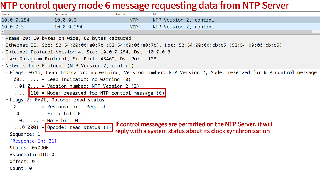
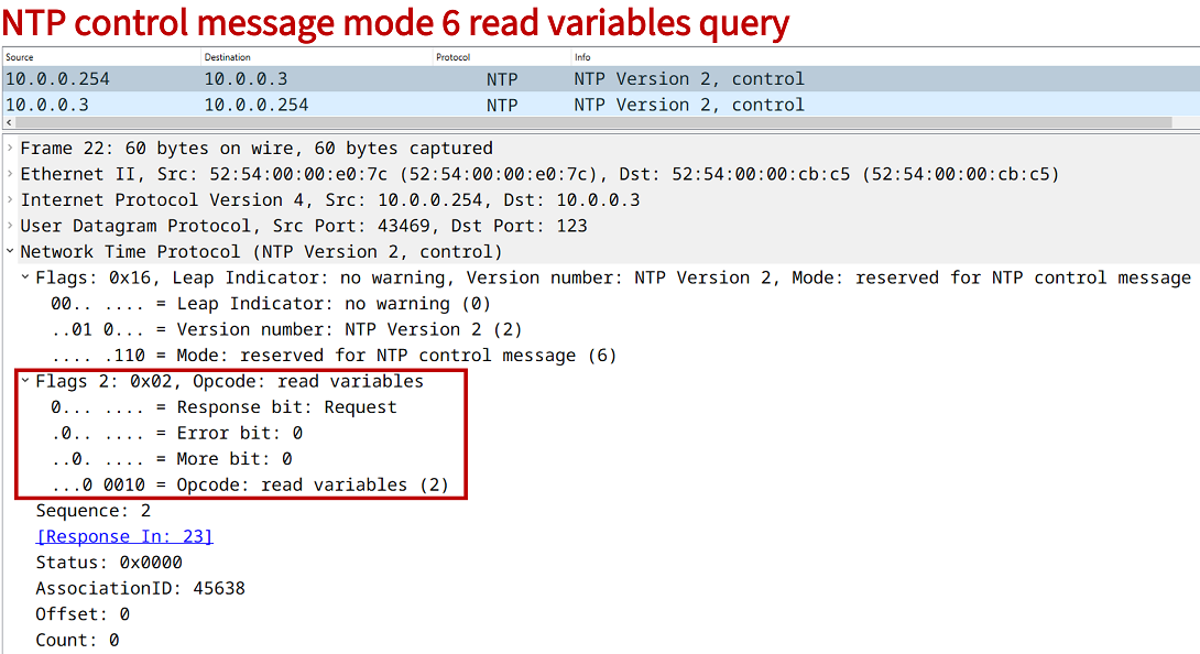
NTP control messages are also called mode 6 queries, and they can be used to request monitoring and system information from an NTP Server. In this example, the Host (10.0.0.254) is a Linux machine and sends two types of queries to R3, which proceeds to block both requests. The first control query is a read status, and the second is a read variables type.
When mode 6 queries are not blocked, the NTP Server R3 returns the requested data as shown in the above Host configuration. As an alternative to using access-lists, control messages can be disabled with the global configuration command no ntp allow mode control. The following debug output from R3 shows a mode 6 control message being blocked by the ACL.
R3#show log | beg Log Buffer
Log Buffer (8192 bytes):

NTP recv pkt on v4 socket, pak = 0x0D7F10D8.
NTP message received from 10.0.0.254 on interface 'GigabitEthernet0/0' (10.0.0.3):

 NTP Header:
   Leap = 00, Version = 2, Mode = 6,
   Stratum = 2,
   Poll Interval = 0,
   Precision = 2,
   Root Delay = 0.0,
   Root Dispersion = 0.0,
   refid = 0.0.0.0,
   Last update reftime = 65532.659969,
   Originated time = 40.167837698,
   Received time = 167837697.67372036,
   Transmit time = 4294311939.65540.
 Hexadecimal equivalent (length = 12):
   0000: 16 02 00 02 00 00 00 00
   0008: 00 00 00 00

NTP Core(DEBUG): ntp_receive: message received
NTP Core(NOTICE): ntp_receive: dropping message: restricted..
The following output from the context-sensitive help feature shows the list of available access-list restrictions that can be used in combination with NTP. A concise description is displayed next to each option.
R3>
R3>enable
R3#configure terminal
Enter configuration commands, one per line.  End with CNTL/Z.
R3(config)#
R3(config)#ntp access-group ipv4 ?
  peer        Provide full access
  query-only  Allow only control queries
  serve       Provide server and query access
  serve-only  Provide only server access
NTP peers
In the following scenario, Site 1 has installed redundant WAN connections, and uses dual internet gateway routers R1 and R2. Both routers synchronize time with public NTP servers, however each router uses a different time source.
R1 synchronizes its time with the NTP servers of the National Metrology Institute of Germany, and specifically prefers the server at ptbtime1.ptb.de. This is accomplished with the global configuration command ntp server ptbtime1.ptb.de prefer on R1. Meanwhile, R2 uses the NTP server at europe.pool.ntp.org.
R1 and R2 provide a redundant NTP service for devices local to Site 1. Namely, R1 and R2 are symmetric active NTP peers of each other in order to ensure time accuracy and redundancy. In an NTP peer configuration a device acts as an NTP Server and also an NTP Client for its associated peer (R1 - R2).
Benefiting from this redundancy, R3 adds both R1 and R2 as NTP servers. R3 uses its Loopback 10 interface address as the source of NTP Client mode packets. The global configuration command ntp source Loopback10 accomplishes this on R3.

Configuration:
R1
R1>
R1>enable
R1#configure terminal
Enter configuration commands, one per line.  End with CNTL/Z.
R1(config)#
R1(config)#ntp server pool.ntp.org
R1(config)#ntp server ptbtime1.ptb.de prefer
R1(config)#ntp server ptbtime2.ptb.de
R1(config)#ntp peer 10.1.0.2
R1(config)#
R1(config)#exit
R1#
R2
R2>
R2>enable
R2#configure terminal
Enter configuration commands, one per line.  End with CNTL/Z.
R2(config)#
R2(config)#ntp server 2.europe.pool.ntp.org
R2(config)#ntp server 3.europe.pool.ntp.org
R2(config)#ntp peer 10.1.0.1
R2(config)#
R2(config)#exit
R2#
R3
R3>
R3>enable
R3#configure terminal
Enter configuration commands, one per line.  End with CNTL/Z.
R3(config)#
R3(config)#interface Loopback10
R3(config-if)#description ** NTP source **
R3(config-if)#ip address 10.3.3.3 255.255.255.255
R3(config-if)#
R3(config-if)#exit
R3(config)#
R3(config)#
R3(config)#router ospf 10
R3(config-router)#router-id 3.3.3.3
R3(config-router)#network 0.0.0.0 0.0.0.0 area 0
R3(config-router)#
R3(config-router)#exit
R3(config)#
R3(config)#
R3(config)#ntp source Loopback10
R3(config)#ntp server 10.0.0.1
R3(config)#ntp server 10.0.0.2
R3(config)#
R3(config)#exit
R3#
#############################################################
##                                                         ##
##                                                         ##
##    In the following NTP outputs, public IP addresses    ##
##    are replaced with hash (#) characters.               ##
##                                                         ##
##                                                         ##
#############################################################


R2#show ntp associations

  address         ref clock       st   when   poll reach  delay  offset   disp
+~10.1.0.1        ###.##.###.###   2     30     64   377  0.860  25.917  2.647                « NTP Peer address
*~##.###.###.###  ###.##.###.###   2     24     64   377 36.703 185.089  2.094
+~###.###.###.##  ##.###.##.###    2     34     64   377 31.407  51.233  6.542
 * sys.peer, # selected, + candidate, - outlyer, x falseticker, ~ configured


R1#show ntp associations

  address         ref clock       st   when   poll reach  delay  offset   disp
+~###.##.###.###  .PTP0.           1     78    128   377 32.041 121.667  3.691
x~10.1.0.2        ###.###.###.##   3     17    128   266  0.348 -22.630  3.351
*~###.##.###.###  .PTP0.           1     72    128   377 32.065 127.975  1.981
x~##.###.###.###  ###.###.##.###   3     69    128   377 10.740  51.113  4.808
 * sys.peer, # selected, + candidate, - outlyer, x falseticker, ~ configured


R1#show ntp associations detail
###.##.###.### configured, ipv4, sane, valid, stratum 1
ref ID .PTP0., time EB8553F5.F0F474F1 (14:32:21.941 UTC Wed Mar 19 2025)
our mode client, peer mode server, our poll intvl 128, peer poll intvl 128
root delay 0.01 msec, root disp 0.01, reach 377, sync dist 59.66
delay 32.04 msec, offset 121.6672 msec, dispersion 3.69, jitter 39.04 msec
precision 2**25, version 4
assoc id 64015, assoc name ptbtime2.ptb.de
assoc in packets 42, assoc out packets 42, assoc error packets 0
org time 00000000.00000000 (00:00:00.000 UTC Mon Jan 1 1900)
rec time EB8553FE.930141F8 (14:32:30.574 UTC Wed Mar 19 2025)
xmt time EB8553FE.930141F8 (14:32:30.574 UTC Wed Mar 19 2025)
filtdelay =    34.35   34.54   34.33   32.84   32.04   43.41   32.58   36.59
filtoffset =  124.99  124.55  119.54  118.55  121.66   91.57   60.90   43.94
filterror =     0.00    0.05    1.86    2.00    3.72    3.95    5.58    5.93
minpoll = 6, maxpoll = 10

10.1.0.2 configured, ipv4, sane, invalid, stratum 3                                  « This is the NTP peer association between R1 and R2
ref ID ###.###.###.## , time EB8552F6.6E3A47CA (14:28:06.430 UTC Wed Mar 19 2025)
our mode active, peer mode active, our poll intvl 128, peer poll intvl 64
root delay 55.86 msec, root disp 87.46, reach 333, sync dist 142.79
delay 0.34 msec, offset -22.6305 msec, dispersion 4.37, jitter 21.86 msec
precision 2**17, version 4
assoc id 64016, assoc name 10.1.0.2
assoc in packets 42, assoc out packets 42, assoc error packets 15
org time EB8553FF.6E753D6D (14:32:31.431 UTC Wed Mar 19 2025)
rec time EB8553F8.6078D463 (14:32:24.376 UTC Wed Mar 19 2025)
xmt time EB8553F8.6078D463 (14:32:24.376 UTC Wed Mar 19 2025)
filtdelay =    11.76    4.91    0.34   16.52    3.36    3.03    7.26    4.17
filtoffset =  -19.60  -23.89  -22.63  -19.65   -4.19    1.80    9.16   14.50
filterror =     0.01    1.02    2.46    3.90    5.34    6.78    8.22    9.66
minpoll = 6, maxpoll = 10

###.##.###.### configured, ipv4, our_master, sane, valid, stratum 1
ref ID .PTP0., time EB8553FE.6D1B384C (14:32:30.426 UTC Wed Mar 19 2025)
our mode client, peer mode server, our poll intvl 128, peer poll intvl 128
root delay 0.10 msec, root disp 0.01, reach 377, sync dist 59.25
delay 32.06 msec, offset 127.9755 msec, dispersion 1.98, jitter 40.37 msec
precision 2**26, version 4
assoc id 64014, assoc name ptbtime1.ptb.de
assoc in packets 42, assoc out packets 42, assoc error packets 0
org time 00000000.00000000 (00:00:00.000 UTC Mon Jan 1 1900)
rec time EB855404.93489557 (14:32:36.575 UTC Wed Mar 19 2025)
xmt time EB855404.93489557 (14:32:36.575 UTC Wed Mar 19 2025)
filtdelay =    32.06   37.02   40.53   37.02   35.36   33.73   37.49   35.59
filtoffset =  127.97  126.78  124.42  119.34  127.16   93.37   66.62   48.20
filterror =     0.00    0.03    1.95    2.07    3.81    4.02    5.67    6.00
minpoll = 6, maxpoll = 10

##.###.###.### configured, ipv4, sane, invalid, stratum 3
ref ID ###.###.##.### , time EB8552C8.95BEB043 (14:27:20.584 UTC Wed Mar 19 2025)
our mode client, peer mode server, our poll intvl 128, peer poll intvl 128
root delay 34.10 msec, root disp 25.23, reach 377, sync dist 120.04
delay 10.74 msec, offset 51.1139 msec, dispersion 4.80, jitter 66.83 msec
precision 2**23, version 4
assoc id 64013, assoc name pool.ntp.org
assoc in packets 42, assoc out packets 42, assoc error packets 0
org time 00000000.00000000 (00:00:00.000 UTC Mon Jan 1 1900)
rec time EB855407.91382F5C (14:32:39.567 UTC Wed Mar 19 2025)
xmt time EB855407.91382F5C (14:32:39.567 UTC Wed Mar 19 2025)
filtdelay =    12.41   11.88   11.87   14.72   14.86   12.83   10.96   10.74
filtoffset =  129.62  130.85  124.84  124.35  127.27   94.84   66.26   51.11
filterror =     0.00    0.03    2.03    2.06    3.89    4.02    5.75    6.03
minpoll = 6, maxpoll = 10


R1#show ntp status
Clock is synchronized, stratum 2, reference is ###.##.###.###                        « R1 is a stratum 2 server, it receives time from a stratum 1 server
nominal freq is 1000.0003 Hz, actual freq is 1000.0588 Hz, precision is 2**17
ntp uptime is 689700 (1/100 of seconds), resolution is 1000
reference time is EB855487.77255427 (14:34:47.465 UTC Wed Mar 19 2025)
clock offset is 127.9755 msec, root delay is 32.17 msec
root dispersion is 154.73 msec, peer dispersion is 2.19 msec
loopfilter state is 'CTRL' (Normal Controlled Loop), drift is -0.000058560 s/s
system poll interval is 128, last update was 106 sec ago.


R3#show ntp status
Clock is synchronized, stratum 4, reference is 10.0.0.2                              « Clock on R3 is synchronized to R2
nominal freq is 1000.0003 Hz, actual freq is 999.7848 Hz, precision is 2**17
ntp uptime is 333000 (1/100 of seconds), resolution is 1001
reference time is EB8556D4.DFF2D567 (14:44:36.874 UTC Wed Mar 19 2025)
clock offset is 35.0223 msec, root delay is 41.41 msec
root dispersion is 4236.05 msec, peer dispersion is 1937.55 msec
loopfilter state is 'CTRL' (Normal Controlled Loop), drift is 0.000215478 s/s
system poll interval is 64, last update was 25 sec ago.


R3#show ntp associations

  address         ref clock       st   when   poll reach  delay  offset   disp
+~10.0.0.1        ###.##.###.###   2     41     64     1  1.172 -168.00 3937.5       « R3 has two NTP servers configured (R1 and R2)
*~10.0.0.2        ##.###.###.###   3     39     64     1  0.547  35.022 1937.5
 * sys.peer, # selected, + candidate, - outlyer, x falseticker, ~ configured
NTP broadcast
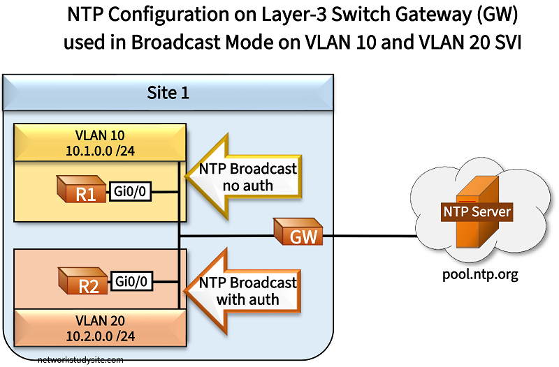
In the following example scenario, the gateway (GW) device is a Layer-3 switch which receives its time from the public NTP servers at pool.ntp.org. In turn, the GW device brodcasts NTP packets from two Switch Virtual Interfaces (SVI), one SVI for VLAN 10, and another for VLAN 20. This is how R1 and R2 can synchronize their time.
The interface-level command ntp broadcast destination 10.1.0.255 on the SVI VLAN 10 sends NTP broadcast mode packets to the VLAN 10 broadcast address. In order to make the NTP client synchronize its time through NTP broadcast packets, the interface-level command ntp broadcast client is applied on R1.
Meanwhile, for VLAN 20 the GW device sends authenticated NTP broadcast packets. For this to work, an authentication key ID with a password is configured on both the GW and on R2 (NTP client). Also, the GW and R2 need to trust the same key ID, which has the value 200 in this example. Then, on the GW SVI VLAN 20 the command ntp broadcast key 200 destination 10.2.0.255 is applied. And on the NTP client R2 the same interface-level command is issued as on R1.
Configuration:
GW
GW>
GW>enable
GW#configure terminal
Enter configuration commands, one per line.  End with CNTL/Z.
GW(config)#
GW(config)#vlan 10
GW(config-vlan)#name VLAN10
GW(config-vlan)#exit
GW(config)#
GW(config)#
GW(config)#vlan 20
GW(config-vlan)#name VLAN20
GW(config-vlan)#exit
GW(config)#
GW(config)#
GW(config)#interface GigabitEthernet0/0
GW(config-if)#description ** Site 1 LAN interface to R1 and R2 **
GW(config-if)#switchport trunk encapsulation dot1q
GW(config-if)#switchport mode trunk
GW(config-if)#switchport trunk allowed vlan 10,20
GW(config-if)#exit
GW(config)#
GW(config)#
GW(config)#interface GigabitEthernet0/1
GW(config-if)#description ** WAN interface to public NTP servers **
GW(config-if)#no switchport
GW(config-if)#ip address dhcp
GW(config-if)#exit
GW(config)#
GW(config)#
GW(config)#ip domain-lookup
GW(config)#
GW(config)#
GW(config)#ntp server 0.europe.pool.ntp.org
Translating "0.europe.pool.ntp.org"...domain server (192.168.0.1) [OK]
i
GW(config)#
GW(config)#ntp server 1.europe.pool.ntp.org
Translating "1.europe.pool.ntp.org"...domain server (192.168.0.1) [OK]
i
GW(config)#
GW(config)#ntp server 2.europe.pool.ntp.org
Translating "2.europe.pool.ntp.org"...domain server (192.168.0.1) [OK]
i
GW(config)#
GW(config)#ntp server 3.europe.pool.ntp.org
Translating "3.europe.pool.ntp.org"...domain server (192.168.0.1) [OK]
i
GW(config)#
GW(config)#
GW(config)#ntp authentication-key 200 md5 P4SSW0RD
GW(config)#ntp trusted-key 200
GW(config)#
GW(config)#
GW(config)#interface Vlan10
GW(config-if)#description ** SVI for VLAN 10 **
GW(config-if)#ip address 10.1.0.2 255.255.255.0
GW(config-if)#ntp broadcast destination 10.1.0.255
GW(config-if)#no shutdown
GW(config-if)#exit
GW(config)#
GW(config)#
GW(config)#interface Vlan20
GW(config-if)#description ** SVI for VLAN 20 **
GW(config-if)#ip address 10.2.0.2 255.255.255.0
GW(config-if)#ntp broadcast key 200 destination 10.2.0.255
GW(config-if)#no shutdown
GW(config-if)#exit
GW(config)#exit
GW#
R1
R1>
R1>enable
R1#configure terminal
Enter configuration commands, one per line.  End with CNTL/Z.
R1(config)#
R1(config)#interface GigabitEthernet0/0
R1(config-if)#ip address 10.1.0.1 255.255.255.0
R1(config-if)#ntp broadcast client
R1(config-if)#exit
R1(config)#exit
R1#
R2
R2>
R2>enable
R2#configure terminal
Enter configuration commands, one per line.  End with CNTL/Z.
R2(config)#
R2(config)#ntp authentication-key 200 md5 P4SSW0RD
R2(config)#ntp trusted-key 200
R2(config)#
R2(config)#interface GigabitEthernet0/0
R2(config-if)#ip address 10.2.0.1 255.255.255.0
R2(config-if)#ntp broadcast client
R2(config-if)#exit
R2(config)#exit
R2#
R1#show ntp status
Clock is synchronized, stratum 4, reference is 10.1.0.2                               « GW VLAN 10 SVI
nominal freq is 1000.0003 Hz, actual freq is 1000.0108 Hz, precision is 2**17
ntp uptime is 2936500 (1/100 of seconds), resolution is 1000
reference time is EB86F12B.431D3594 (19:55:23.262 UTC Thu Mar 20 2025)
clock offset is 7.5416 msec, root delay is 32.62 msec
root dispersion is 7974.05 msec, peer dispersion is 7937.50 msec
loopfilter state is 'CTRL' (Normal Controlled Loop), drift is -0.000010521 s/s
system poll interval is 64, last update was 17 sec ago.


R2#show ntp status
Clock is synchronized, stratum 4, reference is 10.2.0.2                               « GW VLAN 20 SVI
nominal freq is 1000.0003 Hz, actual freq is 999.7922 Hz, precision is 2**17
ntp uptime is 2676500 (1/100 of seconds), resolution is 1001
reference time is EB86F135.5B1B403A (19:55:33.355 UTC Thu Mar 20 2025)
clock offset is -85.3951 msec, root delay is 32.62 msec
root dispersion is 8052.09 msec, peer dispersion is 7937.50 msec
loopfilter state is 'CTRL' (Normal Controlled Loop), drift is 0.000208007 s/s
system poll interval is 64, last update was 18 sec ago.


R2#show ntp associations detail
10.2.0.2 dynamic, ipv4, our_master, sane, valid, stratum 3                            « Keyword "dynamic", instead of "configured"
ref ID ###.###.###.###, time EB86F08D.49B97D85 (19:52:45.287 UTC Thu Mar 20 2025)     « Public NTP server IP address replaced with #
our mode xcast client, peer mode xcast server, our poll intvl 64, peer poll intvl 64  « Broadcast/Multicast mode NTP being used
root delay 32.62 msec, root disp 28.90, reach 1, sync dist 7983.20
delay 0.00 msec, offset -85.3951 msec, dispersion 7937.50, jitter 0.00 msec
precision 2**17, version 4
assoc id 53684, assoc name 10.2.0.2
assoc in packets 406, assoc out packets 2, assoc error packets 0
org time 00000000.00000000 (00:00:00.000 UTC Mon Jan 1 1900)
rec time 00000000.00000000 (00:00:00.000 UTC Mon Jan 1 1900)
xmt time EB86F135.453ECAA0 (19:55:33.270 UTC Thu Mar 20 2025)
filtdelay =     0.00    0.00    0.00    0.00    0.00    0.00    0.00    0.00
filtoffset =  -85.39    0.00    0.00    0.00    0.00    0.00    0.00    0.00
filterror =     0.01 16000.0 16000.0 16000.0 16000.0 16000.0 16000.0 16000.0
minpoll = 6, maxpoll = 6
Note that an alternative configuration would be to apply the interface-level command ntp broadcast on the SVI interface, which would send NTP broadcast packets to the IP address 255.255.255.255.
NTP multicast
In the following example scenario, the Site 1 gateway router (GW) receives its time synchronization from the public NTP servers at pool.ntp.org. In turn, the GW router uses NTP multicast mode to advertise time information within Site 1.
The multicast address 239.1.1.1 is chosen for NTP packets sent in Site 1. Note the IANA has assigned the multicast destination address 224.0.1.1 for NTP, but an arbitrary multicast address can also be used as shown in this example.
Compared to NTP in broadcast mode, a benefit of multicast NTP is the possibility to transmit time information beyond the local subnetwork. This is shown here with R2 and R3 which have ip multicast-routing enabled, PIM Dense Mode enabled, and also OSPF configured. Enabling multicast routing/PIM and OSPF is also needed on the GW router so NTP packets can reach R3.

Configuration:
GW
GW>
GW>enable
GW#configure terminal
Enter configuration commands, one per line.  End with CNTL/Z.
GW(config)#
GW(config)#interface GigabitEthernet0/1
GW(config-if)#description ** to public NTP servers **
GW(config-if)#ip address dhcp
GW(config-if)#no shutdown
GW(config-if)#exit
GW(config)#
GW(config)#
GW(config)#interface GigabitEthernet0/0
GW(config-if)#description ** to LAN R1 and R2 **
GW(config-if)#ip address 10.1.0.3 255.255.255.0
GW(config-if)#ip pim dense-mode
GW(config-if)#ntp multicast 239.1.1.1
GW(config-if)#no shutdown
GW(config-if)#exit
GW(config)#
GW(config)#
GW(config)#ip multicast-routing
GW(config)#
GW(config)#
GW(config)#ip domain-lookup
GW(config)#
GW(config)#
GW(config)#ntp server 0.europe.pool.ntp.org
GW(config)#ntp server 1.europe.pool.ntp.org
GW(config)#ntp server 2.europe.pool.ntp.org
GW(config)#ntp server 3.europe.pool.ntp.org
GW(config)#
GW(config)#
GW(config)#router ospf 10
GW(config-router)#router-id 10.3.3.3
GW(config-router)#network 10.1.0.0 0.0.0.255 area 0
GW(config-router)#exit
GW(config)#exit
GW#
R1
R1>
R1>enable
R1#configure terminal
Enter configuration commands, one per line.  End with CNTL/Z.
R1(config)#
R1(config)#interface GigabitEthernet0/0
R1(config-if)#description ** to GW **
R1(config-if)#ip address 10.1.0.1 255.255.255.0
R1(config-if)#ntp multicast client 239.1.1.1
R1(config-if)#no shutdown
R1(config-if)#exit
R1(config)#exit
R1#
R2
R2>
R2>enable
R2#configure terminal
Enter configuration commands, one per line.  End with CNTL/Z.
R2(config)#
R2(config)#ip multicast-routing
R2(config)#
R2(config)#
R2(config)#interface GigabitEthernet0/0
R2(config-if)#description ** to GW **
R2(config-if)#ip address 10.1.0.2 255.255.255.0
R2(config-if)#ip pim dense-mode
R2(config-if)#ntp multicast client 239.1.1.1
R2(config-if)#no shutdown
R2(config-if)#exit
R2(config)#
R2(config)#
R2(config)#interface GigabitEthernet0/1
R2(config-if)#description ** to R3 **
R2(config-if)#ip address 10.2.0.2 255.255.255.252
R2(config-if)#ip pim dense-mode
R2(config-if)#no shutdown
R2(config-if)#exit
R2(config)#
R2(config)#
R2(config)#router ospf 10
R2(config-router)#router-id 2.2.2.2
R2(config-router)#network 0.0.0.0 255.255.255.255 area 0
R2(config-router)#exit
R2(config)#exit
R2#
R3
R3>
R3>enable
R3#configure terminal
Enter configuration commands, one per line.  End with CNTL/Z.
R3(config)#
R3(config)#ip multicast-routing
R3(config)#
R3(config)#
R3(config)#interface GigabitEthernet0/0
R3(config-if)#description ** to R2 **
R3(config-if)#ip address 10.2.0.1 255.255.255.252
R3(config-if)#ip pim dense-mode
R3(config-if)#ntp multicast client 239.1.1.1
R3(config-if)#no shutdown
R3(config-if)#exit
R3(config)#
R3(config)#
R3(config)#router ospf 10
R3(config-router)#router-id 3.3.3.3
R3(config-router)#network 0.0.0.0 255.255.255.255 area 0
R3(config-router)#exit
R3(config)#exit
R3#
#############################################################
##                                                         ##
##                                                         ##
##    In the following NTP outputs, public IP addresses    ##
##    are replaced with hash (#) characters.               ##
##                                                         ##
##                                                         ##
#############################################################


R3#show ntp associations detail
10.1.0.3 dynamic, ipv4, our_master, sane, valid, stratum 4                        « R3 synchronizes with NTP server in different subnet using multicast
ref ID ###.###.###.###, time EB8813AB.66B0892C (16:34:51.401 UTC Fri Mar 21 2025)
our mode xcast client, peer mode xcast server, our poll intvl 64, peer poll intvl 64    « Broadcast/Multicast Mode NTP being used
root delay 25.00 msec, root disp 238.40, reach 340, sync dist 2240.72
delay 0.00 msec, offset 40.7293 msec, dispersion 1941.60, jitter 47.82 msec
precision 2**17, version 4
assoc id 65088, assoc name 10.1.0.3
assoc in packets 24, assoc out packets 9, assoc error packets 0
org time 00000000.00000000 (00:00:00.000 UTC Mon Jan 1 1900)
rec time 00000000.00000000 (00:00:00.000 UTC Mon Jan 1 1900)
xmt time EB88140C.6C761489 (16:36:28.423 UTC Fri Mar 21 2025)
filtdelay =     0.00    0.00    0.00    0.00    0.00    0.00    0.00    0.00
filtoffset =    0.00    0.00   40.72  -25.26   25.94    0.00    0.00    0.00
filterror =  16000.0 16000.0    4.13    5.10    6.08 16000.0 16000.0 16000.0
minpoll = 6, maxpoll = 6


R3#show ntp associations

  address         ref clock       st   when   poll reach  delay  offset   disp
* 10.1.0.3        ###.###.###.###  4    313     64   340  0.000  40.729 1941.6
 * sys.peer, # selected, + candidate, - outlyer, x falseticker, ~ configured


R3#show ntp status
Clock is synchronized, stratum 5, reference is 10.1.0.3                           « Clock on R3 synchronized with NTP server, R3 is a stratum 5 device
nominal freq is 1000.0003 Hz, actual freq is 999.5003 Hz, precision is 2**16
ntp uptime is 748700 (1/100 of seconds), resolution is 1001
reference time is EB88140C.6208D834 (16:36:28.382 UTC Fri Mar 21 2025)
clock offset is 40.7293 msec, root delay is 25.00 msec
root dispersion is 2269.81 msec, peer dispersion is 1941.60 msec
loopfilter state is 'CTRL' (Normal Controlled Loop), drift is 0.000499961 s/s
system poll interval is 64, last update was 323 sec ago.


R1#show ntp status
Clock is synchronized, stratum 5, reference is 10.1.0.3                           « R1 is also synchronized, in same subnet as GW, no need for PIM
nominal freq is 1000.0003 Hz, actual freq is 1000.0008 Hz, precision is 2**16
ntp uptime is 16800 (1/100 of seconds), resolution is 1000
reference time is EB8809D5.F5F85D34 (15:52:53.960 UTC Fri Mar 21 2025)
clock offset is -49.8439 msec, root delay is 28.75 msec
root dispersion is 4209.63 msec, peer dispersion is 3937.52 msec
loopfilter state is 'CTRL' (Normal Controlled Loop), drift is -0.000000588 s/s
system poll interval is 64, last update was 72 sec ago.
If the NTP multicast client is in the same subnet as the NTP server, then IP multicast routing and PIM do not need to be enabled. Furthermore, if the interface-level command ntp multicast is applied on an NTP server, then it will start sending NTP packets to the multicast address 224.0.1.1 defined by IANA.
NTP with IPv6
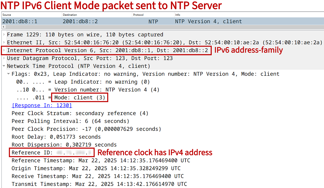
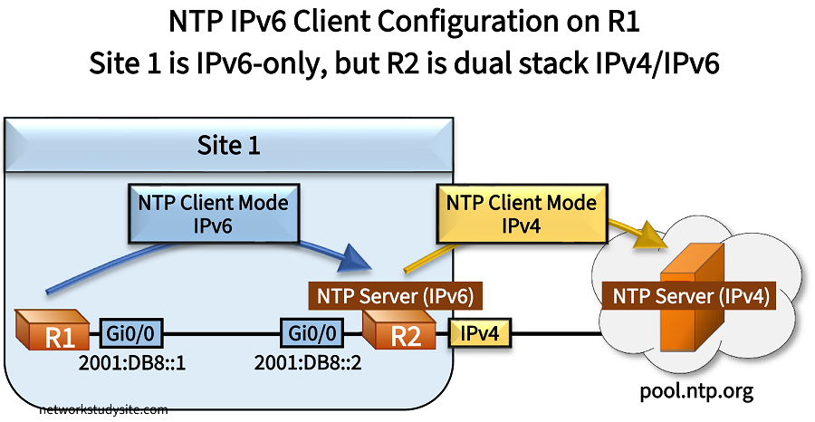
In the following example, Site 1 uses IPv6-only between R1 and R2. R2 connects to the internet with an IPv4-only connection. R2 requests the time from the public NTP servers at ntp.pool.org. In turn, R1 requests the time from R2 using NTP IPv6 Client Mode packets.
So, although R2 has synchronized its own time with NTP IPv4, it does reply with NTP IPv6 Server Mode packets to R1, and is able to provide accurate time over IPv6. This means, R2 is a dual stack IPv4/IPv6 router, an IPv4 NTP Client, and an IPv6 NTP Server.
Configuration:
R2 (NTP IPv6 server)
R2>
R2>enable
R2#configure terminal
Enter configuration commands, one per line.  End with CNTL/Z.
R2(config)#
R2(config)#interface GigabitEthernet0/0
R2(config-if)#description ** to R1 **
R2(config-if)#ipv6 address 2001:DB8::2/64
R2(config-if)#ipv6 address FE80::2 link-local
R2(config-if)#exit
R2(config)#
R2(config)#
R2(config)#interface GigabitEthernet0/1
R2(config-if)#description ** to public NTP IPv4 servers **
R2(config-if)#ip address dhcp
R2(config-if)#exit
R2(config)#
R2(config)#
R2(config)#ntp server 0.europe.pool.ntp.org
R2(config)#ntp server 3.europe.pool.ntp.org
R2(config)#ntp server 1.europe.pool.ntp.org
R2(config)#ntp server 2.europe.pool.ntp.org
R2(config)#
R2(config)#
R2(config)#exit
R2#
R1 (NTP IPv6 client)
R1>
R1>enable
R1#configur terminal
Enter configuration commands, one per line.  End with CNTL/Z.
R1(config)#
R1(config)#interface GigabitEthernet0/0
R1(config-if)#description ** to R2 - NTP IPv6 server **
R1(config-if)#ipv6 address 2001:DB8::1/64
R1(config-if)#ipv6 address FE80::1 link-local
R1(config-if)#exit
R1(config)#
R1(config)#
R1(config)#ntp server 2001:DB8::2
R1(config)#
R1(config)#
R1(config)#exit
R1#
#############################################################
##                                                         ##
##                                                         ##
##    In the following NTP outputs, public IP addresses    ##
##    are replaced with hash (#) characters.               ##
##                                                         ##
##                                                         ##
#############################################################


R1#show ntp associations detail
2001:DB8::2 configured, ipv6, our_master, sane, valid, stratum 3                  « NTP IPv6 server address is configured on R1
ref ID ###.##.##.###  , time EB8946EA.B52842EF (14:25:46.707 UTC Sat Mar 22 2025)
our mode client, peer mode server, our poll intvl 64, peer poll intvl 64
root delay 39.26 msec, root disp 95.42, reach 77, sync dist 194.68
delay 0.67 msec, offset -50.9007 msec, dispersion 2.24, jitter 76.68 msec
precision 2**17, version 4
assoc id 40258, assoc name 2001:DB8::2
assoc in packets 30, assoc out packets 30, assoc error packets 0
org time 00000000.00000000 (00:00:00.000 UTC Mon Jan 1 1900)
rec time EB894785.45AE6BC7 (14:28:21.272 UTC Sat Mar 22 2025)
xmt time EB894785.45AE6BC7 (14:28:21.272 UTC Sat Mar 22 2025)
filtdelay =     0.67    2.40    0.99    0.80    1.56    1.55    0.86    1.95
filtoffset =  -50.90  -54.71  -11.44   35.65   39.50   39.42   39.89   35.83
filterror =     0.01    1.29    2.73    4.17    5.61    5.62    5.64    6.55
minpoll = 6, maxpoll = 10


R1#show ntp association

  address         ref clock       st   when   poll reach  delay  offset   disp
*~2001:DB8::2     ###.##.##.###    3     36     64    77  0.672 -50.900  2.245
 * sys.peer, # selected, + candidate, - outlyer, x falseticker, ~ configured


R1#show ntp status
Clock is synchronized, stratum 4, reference is ##.##.###.#                        « Clock is synchronized using NTP IPv6
nominal freq is 1000.0003 Hz, actual freq is 1000.0285 Hz, precision is 2**17
ntp uptime is 405100 (1/100 of seconds), resolution is 1000
reference time is EB894785.52CC4A85 (14:28:21.323 UTC Sat Mar 22 2025)
clock offset is -50.9007 msec, root delay is 39.93 msec
root dispersion is 225.84 msec, peer dispersion is 2.24 msec
loopfilter state is 'CTRL' (Normal Controlled Loop), drift is -0.000028247 s/s
system poll interval is 64, last update was 39 sec ago.
Maximum associations
With the global configuration mode command ntp max-associations the number of NTP server and NTP peer associations can be limited. The default value is set to 100. As shown in the following outputs, when the maximum configured limit of NTP associations is exceeded, a new server or peer can no longer be added.
R1>
R1>enable
R1#configure terminal
Enter configuration commands, one per line.  End with CNTL/Z.
R1(config)#
R1(config)#ntp max-associations 1
R1(config)#
R1(config)#
R1(config)#ntp server 10.0.0.2
R1(config)#ntp server 10.0.0.3
%NTP: Did not configure peer.  Too many peers(2). Allowed only 1
%NTP: Couldn't configure peer
R1(config)#
R1(config)#
R1(config)#ntp peer 10.0.0.3
%NTP: Did not configure master clock.  Too many peers(2). Allowed only 1
%NTP: Couldn't configure peer
R1(config)#
R1(config)#
R1(config)#ntp max-associations 100
R1(config)#
R1(config)#
R1(config)#ntp server 10.0.0.3
R1(config)#ntp peer 10.0.0.4
R1(config)#
R1(config)#
R1(config)#exit
R1#
R1#
R1#show run | section ^ntp
ntp server 10.0.0.2
ntp server 10.0.0.3
ntp peer 10.0.0.4
R1#
What is the difference between the hardware clock and the system clock?
The hardware clock and the software clock are two mechanisms for providing the time on a Cisco router. The hardware clock is also called the calender, and it measures time even when a network device is turned off or being rebooted. On the other hand, a software clock is synchronized using the network device's operating system.
The software clock is commonly updated/synchronized using NTP. However, the hardware clock can also be updated through NTP by issuing the following command in global configuration mode.
R1>
R1>enable
R1#configure terminal
Enter configuration commands, one per line.  End with CNTL/Z.
R1(config)#
R1(config)#ntp update-calendar
R1(config)#
R1(config)#exit
R1#
R1#show calendar
17:20:30 UTC Sat Mar 22 2025
R1#
R1#show clock
17:20:36.360 UTC Sat Mar 22 2025
R1#
In the above outputs, the show calendar command refers to the hardware clock which will be updated using the time synchronized by NTP. Note that the time between the hardware and the software clock on a local device can be synchronized using the following commands.
R1>
R1>enable
R1#
R1#
R1#clock ?
  read-calendar    Read the hardware calendar into the clock
  set              Set the time and date
  update-calendar  Update the hardware calendar from the clock

R1#
R1#