OSPF Virtual Link Example Configuration
Table of Contents
Jump to section:
- What is OSPF Virtual Link? ‹
- What is an OSPF transit area? ‹
- What is the disadvantage of OSPF Virtual Links? ‹
- OSPF Virtual Link configuration - adding disconnected area ‹
- OSPF Virtual Link configuration - adding a backbone area ‹
- GRE Tunnel instead of Virtual Link ‹
- Download section ‹
What is OSPF Virtual Link?
An OSPF Virtual Link enables chaining two non-backbone areas together while preserving connectivity to the backbone area. This is especially useful considering the default requirement of OSPF. Namely, there cannot be an OSPF non-backbone area which is only connected to another non-backbone area. In such a scenario, if two non-backbone areas are connected the OSPF network will not converge.
An OSPF Virtual Link provides a solution by overriding this default requirement. Configuration is performed on the Area Border Routers (ABR) seperating the non-backbone OSPF areas from each other, and as a result the two ABRs establish a neighborship. The corresponding RFC 2328 provides a name for this neighborship, it is quoted below.
Such an adjacency has been referred to in this document as a "virtual adjacency".
RFC 2328, OSPF Version 2
What is an OSPF transit area?
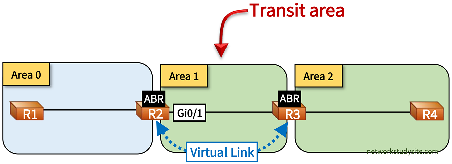
An OSPF transit area provides connectivity for a Virtual Link between two Area Border Routers (ABR). Thus, two ABRs are connected to a common transit area when establishing a Virtual Link. The OSPF cost between the two ABRs is used as the Virtual Link's cost.
R2#show ip ospf virtual-links | i Transit
  Transit area 1, via interface GigabitEthernet0/1
What is the disadvantage of OSPF Virtual Links?
OSPF Virtual Links can solve unexpected design situations arising from necessity rather than upfront planning. The traditional hierarchical design of OSPF can be complicated with Virtual Links which can make troubleshooting more difficult. OSPF Virtual Links cannot be configured across stub areas and doing so will prompt the router to display the following message. A GRE Tunnel can be used instead to share OSPF routes between disconnected or discontiguous areas.
Router#
Router#configure terminal
Enter configuration commands, one per line.  End with CNTL/Z.
Router(config)#router ospf 10
Router(config-router)#area 1 virtual-link 2.2.2.2
% OSPF: Virtual links are not allowed in NSSA and stub areas
OSPF Virtual Link configuration - adding disconnected area
In the following example topology, the OSPF area 2 is connected with a Virtual Link to OSPF area 0. This is achieved through area 1, which provides connectivity between the Area Border Routers (ABR) R2 and R3. The OSPF Virtual Link terminates on R2 and R3. Thus, area 1 becomes a transit area.

Configuration:
R1
R1#show run int Lo10 | sec int
interface Loopback10
 ip address 10.0.0.9 255.255.255.248
 ip ospf network point-to-point

R1#show run int Lo20 | sec int
interface Loopback20
 ip address 10.0.0.17 255.255.255.248
 ip ospf network point-to-point

R1#show run int Gi0/0 | sec int
interface GigabitEthernet0/0
 description ** to R2 **
 ip address 10.0.0.1 255.255.255.252
 ip ospf network point-to-point
 duplex auto
 speed auto
 media-type rj45

R1#show run | sec router
router ospf 10
 router-id 1.1.1.1
 network 10.0.0.0 0.0.0.3 area 0
 network 10.0.0.8 0.0.0.7 area 0
 network 10.0.0.16 0.0.0.7 area 0
R2
R2#show run int Gi0/0 | sec int
interface GigabitEthernet0/0
 description ** to R1 **
 ip address 10.0.0.2 255.255.255.252
 ip ospf network point-to-point
 duplex auto
 speed auto
 media-type rj45

R2#show run int Gi0/1 | sec int
interface GigabitEthernet0/1
 description ** to R3 **
 ip address 10.1.0.1 255.255.255.252
 ip ospf network point-to-point
 duplex auto
 speed auto
 media-type rj45

R2#show run | sec router ospf
router ospf 10
 router-id 2.2.2.2
 area 1 virtual-link 3.3.3.3
 network 10.0.0.0 0.0.0.3 area 0
 network 10.1.0.0 0.0.0.3 area 1
R3
R3#show run int Gi0/0 | sec int
interface GigabitEthernet0/0
 description ** to R2 **
 ip address 10.1.0.2 255.255.255.252
 ip ospf network point-to-point
 duplex auto
 speed auto
 media-type rj45

R3#show run int Gi0/1 | sec int
interface GigabitEthernet0/1
 description ** to R4 **
 ip address 10.2.0.1 255.255.255.252
 ip ospf network point-to-point
 duplex auto
 speed auto
 media-type rj45

R3#show run | sec router
router ospf 10
 router-id 3.3.3.3
 area 1 virtual-link 2.2.2.2
 network 10.1.0.0 0.0.0.3 area 1
 network 10.2.0.0 0.0.0.3 area 2
R4
R4#show run int Lo10 | sec int
interface Loopback10
 ip address 10.2.0.9 255.255.255.248
 ip ospf network point-to-point

R4#show run int Lo20 | sec int
interface Loopback20
 ip address 10.2.0.17 255.255.255.248
 ip ospf network point-to-point

R4#show run int Gi0/0 | sec int
interface GigabitEthernet0/0
 description ** to R3 **
 ip address 10.2.0.2 255.255.255.252
 ip ospf network point-to-point
 duplex auto
 speed auto
 media-type rj45

R4#show run | sec router
router ospf 10
 router-id 4.4.4.4
 network 10.2.0.0 0.0.0.3 area 2
 network 10.2.0.8 0.0.0.7 area 2
 network 10.2.0.16 0.0.0.7 area 2
R2#show ip ospf neighbor

Neighbor ID     Pri   State           Dead Time   Address         Interface
3.3.3.3           0   FULL/  -           -        10.1.0.2        OSPF_VL0      « OSPF neighborship through Virtual Link
1.1.1.1           0   FULL/  -        00:00:35    10.0.0.1        GigabitEthernet0/0
3.3.3.3           0   FULL/  -        00:00:38    10.1.0.2        GigabitEthernet0/1


R2#show ip ospf virtual-links
Virtual Link OSPF_VL0 to router 3.3.3.3 is up
  Run as demand circuit
  DoNotAge LSA allowed.
  Transit area 1, via interface GigabitEthernet0/1       « Area 1 is a transit area
 Topology-MTID    Cost    Disabled     Shutdown      Topology Name
        0           1         no          no            Base
  Transmit Delay is 1 sec, State POINT_TO_POINT,
  Timer intervals configured, Hello 10, Dead 40, Wait 40, Retransmit 5
    Hello due in 00:00:07
    Adjacency State FULL (Hello suppressed)
    Index 1/2/3, retransmission queue length 0, number of retransmission 0
    First 0x0(0)/0x0(0)/0x0(0) Next 0x0(0)/0x0(0)/0x0(0)
    Last retransmission scan length is 0, maximum is 0
    Last retransmission scan time is 0 msec, maximum is 0 msec


R1#show ip route ospf | beg Ga
Gateway of last resort is not set

      10.0.0.0/8 is variably subnetted, 10 subnets, 3 masks
O IA     10.1.0.0/30 [110/2] via 10.0.0.2, 00:36:40, GigabitEthernet0/0
O IA     10.2.0.0/30 [110/3] via 10.0.0.2, 00:34:20, GigabitEthernet0/0
O IA     10.2.0.8/29 [110/4] via 10.0.0.2, 00:34:20, GigabitEthernet0/0
O IA     10.2.0.16/29 [110/4] via 10.0.0.2, 00:34:20, GigabitEthernet0/0


R1#show ip ospf database

            OSPF Router with ID (1.1.1.1) (Process ID 10)

                Router Link States (Area 0)

Link ID         ADV Router      Age         Seq#       Checksum Link count
1.1.1.1         1.1.1.1         753         0x80000004 0x00D4E8 4
2.2.2.2         2.2.2.2         647         0x80000006 0x00A02B 3
3.3.3.3         3.3.3.3         2     (DNA) 0x80000002 0x000101 1

                Summary Net Link States (Area 0)

Link ID         ADV Router      Age         Seq#       Checksum
10.1.0.0        2.2.2.2         647         0x80000002 0x00B476
10.1.0.0        3.3.3.3         2     (DNA) 0x80000002 0x009690
10.2.0.0        3.3.3.3         8     (DNA) 0x80000001 0x008C9A
10.2.0.8        3.3.3.3         2     (DNA) 0x80000002 0x002CF4
10.2.0.16       3.3.3.3         2     (DNA) 0x80000002 0x00DB3D
As visible in the above output, R1 receives prefixes originating in area 2. The prefixes are advertised as inter-area Type-3 summary LSAs, and they use the Virtual Link between R2 - R3 to reach area 0. The following output shows that connectivity works end-to-end.
R1#ping 10.2.0.17 source 10.0.0.9
Type escape sequence to abort.
Sending 5, 100-byte ICMP Echos to 10.2.0.17, timeout is 2 seconds:
Packet sent with a source address of 10.0.0.9
!!!!!
Success rate is 100 percent (5/5), round-trip min/avg/max = 2/2/3 ms


R1#trace 10.2.0.9 source 10.0.0.17 probe 1
Type escape sequence to abort.
Tracing the route to 10.2.0.9
VRF info: (vrf in name/id, vrf out name/id)
  1 10.0.0.2 2 msec
  2 10.1.0.2 1 msec
  3 10.2.0.2 3 msec
OSPF Virtual Link configuration - adding a backbone area
In the following example, the OSPF backbone area is divided by area 1, creating a discontiguous backbone. To overcome the routing issues caused by such a design, a Virtual Link is configured across area 1, connecting the two OSPF backbone areas. The Virtual Link is configured between the ABR routers R2 and R3. Thus, area 1 becomes a transit area. As a result of the OSPF Virtual Link, end-to-end connectivity is achieved between R1 and R5.

Configuration:
R1
R1#show run int Lo10 | sec int
interface Loopback10
 ip address 10.0.1.9 255.255.255.248
 ip ospf network point-to-point

R1#show run int Lo20 | sec int
interface Loopback20
 ip address 10.0.1.17 255.255.255.248
 ip ospf network point-to-point

R1#show run int Gi0/0 | sec int
interface GigabitEthernet0/0
 description ** to R2 **
 ip address 10.0.1.1 255.255.255.252
 ip ospf network point-to-point
 duplex auto
 speed auto
 media-type rj45

R1#show run | sec router
router ospf 10
 router-id 1.1.1.1
 network 10.0.1.0 0.0.0.3 area 0
 network 10.0.1.8 0.0.0.7 area 0
 network 10.0.1.16 0.0.0.7 area 0
R2
R2#show run int Gi0/0 | sec int
interface GigabitEthernet0/0
 description ** to R1 **
 ip address 10.0.1.2 255.255.255.252
 ip ospf network point-to-point
 duplex auto
 speed auto
 media-type rj45

R2#show run int Gi0/1 | sec int
interface GigabitEthernet0/1
 description ** to R3 **
 ip address 10.1.0.1 255.255.255.252
 ip ospf network point-to-point
 duplex auto
 speed auto
 media-type rj45

R2#show run | sec router
router ospf 10
 router-id 2.2.2.2
 area 1 virtual-link 3.3.3.3
 network 10.0.1.0 0.0.0.3 area 0
 network 10.1.0.0 0.0.0.3 area 1
R3
R3#show run int Gi0/0 | sec int
interface GigabitEthernet0/0
 description ** to R2 **
 ip address 10.1.0.2 255.255.255.252
 ip ospf network point-to-point
 duplex auto
 speed auto
 media-type rj45

R3#show run int Gi0/1 | sec int
interface GigabitEthernet0/1
 description ** to R4 **
 ip address 10.0.2.1 255.255.255.252
 ip ospf network point-to-point
 duplex auto
 speed auto
 media-type rj45

R3#show run | sec router
router ospf 10
 router-id 3.3.3.3
 area 1 virtual-link 2.2.2.2
 network 10.0.2.0 0.0.0.3 area 0
 network 10.1.0.0 0.0.0.3 area 1
R4
R4#show run int Gi0/0 | sec int
interface GigabitEthernet0/0
 description ** to R3 **
 ip address 10.0.2.2 255.255.255.252
 ip ospf network point-to-point
 duplex auto
 speed auto
 media-type rj45

R4#show run int Gi0/1 | sec int
interface GigabitEthernet0/1
 description ** to R5 **
 ip address 10.2.0.1 255.255.255.252
 ip ospf network point-to-point
 duplex auto
 speed auto
 media-type rj45

R4#show run | sec router
router ospf 10
 router-id 4.4.4.4
 network 10.0.2.0 0.0.0.3 area 0
 network 10.2.0.0 0.0.0.3 area 2
R5
R5#show run int Lo10 | sec int
interface Loopback10
 ip address 10.2.0.9 255.255.255.248
 ip ospf network point-to-point

R5#show run int Lo20 | sec int
interface Loopback20
 ip address 10.2.0.17 255.255.255.248
 ip ospf network point-to-point

R5#show run int Gi0/0 | sec int
interface GigabitEthernet0/0
 description ** to R4 **
 ip address 10.2.0.2 255.255.255.252
 ip ospf network point-to-point
 duplex auto
 speed auto
 media-type rj45

R5#show run | sec router
router ospf 10
 router-id 5.5.5.5
 network 10.2.0.0 0.0.0.3 area 2
 network 10.2.0.8 0.0.0.7 area 2
 network 10.2.0.16 0.0.0.7 area 2
R2#show ip ospf neighbor

Neighbor ID     Pri   State           Dead Time   Address         Interface
1.1.1.1           0   FULL/  -        00:00:33    10.0.1.1        GigabitEthernet0/0
3.3.3.3           0   FULL/  -           -        10.1.0.2        OSPF_VL0
3.3.3.3           0   FULL/  -        00:00:34    10.1.0.2        GigabitEthernet0/1


R1#show ip route ospf | beg Ga
Gateway of last resort is not set

      10.0.0.0/8 is variably subnetted, 11 subnets, 3 masks
O        10.0.2.0/30 [110/3] via 10.0.1.2, 00:26:24, GigabitEthernet0/0
O IA     10.1.0.0/30 [110/2] via 10.0.1.2, 00:27:01, GigabitEthernet0/0
O IA     10.2.0.0/30 [110/4] via 10.0.1.2, 00:19:35, GigabitEthernet0/0
O IA     10.2.0.8/29 [110/5] via 10.0.1.2, 00:19:30, GigabitEthernet0/0
O IA     10.2.0.16/29 [110/5] via 10.0.1.2, 00:19:30, GigabitEthernet0/0


R1#ping 10.2.0.9 source 10.0.1.17
Type escape sequence to abort.
Sending 5, 100-byte ICMP Echos to 10.2.0.9, timeout is 2 seconds:
Packet sent with a source address of 10.0.1.17
!!!!!
Success rate is 100 percent (5/5), round-trip min/avg/max = 2/2/3 ms


R1#trace 10.2.0.17 source 10.0.1.9 probe 1
Type escape sequence to abort.
Tracing the route to 10.2.0.17
VRF info: (vrf in name/id, vrf out name/id)
  1 10.0.1.2 2 msec
  2 10.1.0.2 2 msec
  3 10.0.2.2 3 msec
  4 10.2.0.2 2 msec
GRE Tunnel instead of Virtual Link
A Virtual Link cannot be configured across an OSPF stub area. The following message is received as a result.
R2#
R2#en
R2#conf t
Enter configuration commands, one per line.  End with CNTL/Z.
R2(config)#router ospf 10
R2(config-router)#area 1 virtual-link 4.4.4.4
% OSPF: Virtual links are not allowed in NSSA and stub areas
In such a scenario, a GRE tunnel can be configured across the stub area 1 to connect OSPF area 2 with the existing backbone area. The GRE tunnel endpoints are terminated at the ABR routers R2 and R4. The GRE tunnel is configured in area 0.

Configuration:
R1
R1#show run int Lo10 | sec int
interface Loopback10
 ip address 10.0.0.9 255.255.255.248
 ip ospf network point-to-point

R1#show run int Lo20 | sec int
interface Loopback20
 ip address 10.0.0.17 255.255.255.248
 ip ospf network point-to-point

R1#show run int Gi0/0 | sec int
interface GigabitEthernet0/0
 description ** to R2 **
 ip address 10.0.0.1 255.255.255.252
 ip ospf network point-to-point
 duplex auto
 speed auto
 media-type rj45

R1#show run | sec router
router ospf 10
 router-id 1.1.1.1
 network 10.0.0.0 0.0.0.3 area 0
 network 10.0.0.8 0.0.0.7 area 0
 network 10.0.0.16 0.0.0.7 area 0
R2
R2#show run int Gi0/0 | sec int
interface GigabitEthernet0/0
 description ** to R1 **
 ip address 10.0.0.2 255.255.255.252
 ip ospf network point-to-point
 duplex auto
 speed auto
 media-type rj45

R2#show run int Gi0/1 | sec int
interface GigabitEthernet0/1
 description ** to R3 **
 ip address 10.1.1.1 255.255.255.252
 ip ospf network point-to-point
 duplex auto
 speed auto
 media-type rj45

R2#show run int Tu10 | sec int
interface Tunnel10
 description ** GRE tunnel to R4 **
 ip address 192.168.0.1 255.255.255.252
 tunnel source GigabitEthernet0/1
 tunnel destination 10.1.2.2

R2#show run | sec router
router ospf 10
 router-id 2.2.2.2
 area 1 stub
 network 10.0.0.0 0.0.0.3 area 0
 network 10.1.1.0 0.0.0.3 area 1
 network 192.168.0.0 0.0.0.3 area 0
R3
R3#show run int Gi0/0 | sec int
interface GigabitEthernet0/0
 description ** to R2 **
 ip address 10.1.1.2 255.255.255.252
 ip ospf network point-to-point
 duplex auto
 speed auto
 media-type rj45

R3#show run int Gi0/1 | sec int
interface GigabitEthernet0/1
 description ** to R4 **
 ip address 10.1.2.1 255.255.255.252
 ip ospf network point-to-point
 duplex auto
 speed auto
 media-type rj45

R3#show run | sec router
router ospf 10
 router-id 3.3.3.3
 area 1 stub
 network 10.1.1.0 0.0.0.3 area 1
 network 10.1.2.0 0.0.0.3 area 1
R4
R4#show run int Gi0/0 | sec int
interface GigabitEthernet0/0
 description ** to R3 **
 ip address 10.1.2.2 255.255.255.252
 ip ospf network point-to-point
 duplex auto
 speed auto
 media-type rj45

R4#show run int Gi0/1 | sec int
interface GigabitEthernet0/1
 description ** to R5 **
 ip address 10.2.0.1 255.255.255.252
 ip ospf network point-to-point
 duplex auto
 speed auto
 media-type rj45

R4#show run | sec router
router ospf 10
 router-id 4.4.4.4
 area 1 stub
 network 10.1.2.0 0.0.0.3 area 1
 network 10.2.0.0 0.0.0.3 area 2
 network 192.168.0.0 0.0.0.3 area 0

R4#show run | sec router
router ospf 10
 router-id 4.4.4.4
 area 1 stub
 network 10.1.2.0 0.0.0.3 area 1
 network 10.2.0.0 0.0.0.3 area 2
 network 192.168.0.0 0.0.0.3 area 0
R5
R5#show run int Lo10 | sec int
interface Loopback10
 ip address 10.2.0.9 255.255.255.248
 ip ospf network point-to-point

R5#show run int Lo20 | sec int
interface Loopback20
 ip address 10.2.0.17 255.255.255.248
 ip ospf network point-to-point

R5#show run int Gi0/0 | sec int
interface GigabitEthernet0/0
 description ** to R4 **
 ip address 10.2.0.2 255.255.255.252
 ip ospf network point-to-point
 duplex auto
 speed auto
 media-type rj45

R5#show run | sec router
router ospf 10
 router-id 5.5.5.5
 network 10.2.0.0 0.0.0.3 area 2
 network 10.2.0.8 0.0.0.7 area 2
 network 10.2.0.16 0.0.0.7 area 2
R2#show ip ospf neighbor

Neighbor ID     Pri   State           Dead Time   Address         Interface
4.4.4.4           0   FULL/  -        00:00:37    192.168.0.2     Tunnel10
1.1.1.1           0   FULL/  -        00:00:33    10.0.0.1        GigabitEthernet0/0
3.3.3.3           0   FULL/  -        00:00:36    10.1.1.2        GigabitEthernet0/1


R2#show ip ospf interface | sec Tunnel
Tunnel10 is up, line protocol is up
  Internet Address 192.168.0.1/30, Area 0, Attached via Network Statement
  Process ID 10, Router ID 2.2.2.2, Network Type POINT_TO_POINT, Cost: 1000
  Topology-MTID    Cost    Disabled    Shutdown      Topology Name
        0           1000      no          no            Base
  Transmit Delay is 1 sec, State POINT_TO_POINT
  Timer intervals configured, Hello 10, Dead 40, Wait 40, Retransmit 5
    oob-resync timeout 40
    Hello due in 00:00:03
  Supports Link-local Signaling (LLS)
  Cisco NSF helper support enabled
  IETF NSF helper support enabled
  Index 1/2/3, flood queue length 0
  Next 0x0(0)/0x0(0)/0x0(0)
  Last flood scan length is 1, maximum is 1
  Last flood scan time is 0 msec, maximum is 0 msec
  Neighbor Count is 1, Adjacent neighbor count is 1
    Adjacent with neighbor 4.4.4.4
  Suppress hello for 0 neighbor(s)


R1#show ip route ospf | beg Ga
Gateway of last resort is not set

      10.0.0.0/8 is variably subnetted, 11 subnets, 3 masks
O IA     10.1.1.0/30 [110/2] via 10.0.0.2, 00:31:22, GigabitEthernet0/0
O IA     10.1.2.0/30 [110/3] via 10.0.0.2, 00:25:43, GigabitEthernet0/0
O IA     10.2.0.0/30 [110/1002] via 10.0.0.2, 00:14:55, GigabitEthernet0/0
O IA     10.2.0.8/29 [110/1003] via 10.0.0.2, 00:14:55, GigabitEthernet0/0
O IA     10.2.0.16/29 [110/1003] via 10.0.0.2, 00:14:55, GigabitEthernet0/0
      192.168.0.0/30 is subnetted, 1 subnets
O        192.168.0.0 [110/1001] via 10.0.0.2, 00:15:05, GigabitEthernet0/0
As shown in the above router output, the OSPF neighborship is formed across the GRE tunnel between R2 and R4. Consequently, R1 receives prefixes from R5 via OSPF. The prefixes are received as inter-area OSPF Type-3 LSAs. Connectivity is thus ensured end-to-end, using a GRE tunnel across a the stub area.
R1#ping 10.2.0.9 source 10.0.0.17
Type escape sequence to abort.
Sending 5, 100-byte ICMP Echos to 10.2.0.9, timeout is 2 seconds:
Packet sent with a source address of 10.0.0.17
!!!!!
Success rate is 100 percent (5/5), round-trip min/avg/max = 2/2/3 ms


R1#trace 10.2.0.17 source 10.0.0.9 probe 1
Type escape sequence to abort.
Tracing the route to 10.2.0.17
VRF info: (vrf in name/id, vrf out name/id)
  1 10.0.0.2 2 msec
  2 192.168.0.2 3 msec
  3 10.2.0.2 3 msec